Apparatus and process for aperturing and stretching a web

a technology of apertures and webs, applied in the direction of dough shaping, manufacturing tools, buttons, etc., can solve the problems of reducing the thickness of some individual fibers, prior art approaches are not suitable for creating webs, and the dimensions of the cross-machine direction of apertures are not wider than the width of the web,

Active Publication Date: 2012-11-08
THE PROCTER & GAMBLE COMPANY
View PDF8 Cites 96 Cited by
  • Summary
  • Abstract
  • Description
  • Claims
  • Application Information

AI Technical Summary

Problems solved by technology

Prior art approaches are not suitable for creating apertures having wider dimensions in the cross-machine direction—particularly with tough or tear-resistant films.
Prior art approaches are also not suitable for creating webs having alternating ridges and grooves, with apertures located in the grooves, using high speed aperturing and stretching means such as that described here.
However, the thickness of some of the individual fibers may decrease as a result of the stretching.
Alternatively, tension could be applied to expand the web, which would result in a decrease in the height and frequency of the ridges and grooves, and decrease the web's overall basis weight.

Method used


Image

  • Apparatus and process for aperturing and stretching a web
  • Apparatus and process for aperturing and stretching a web
  • Apparatus and process for aperturing and stretching a web

Examples


example 1

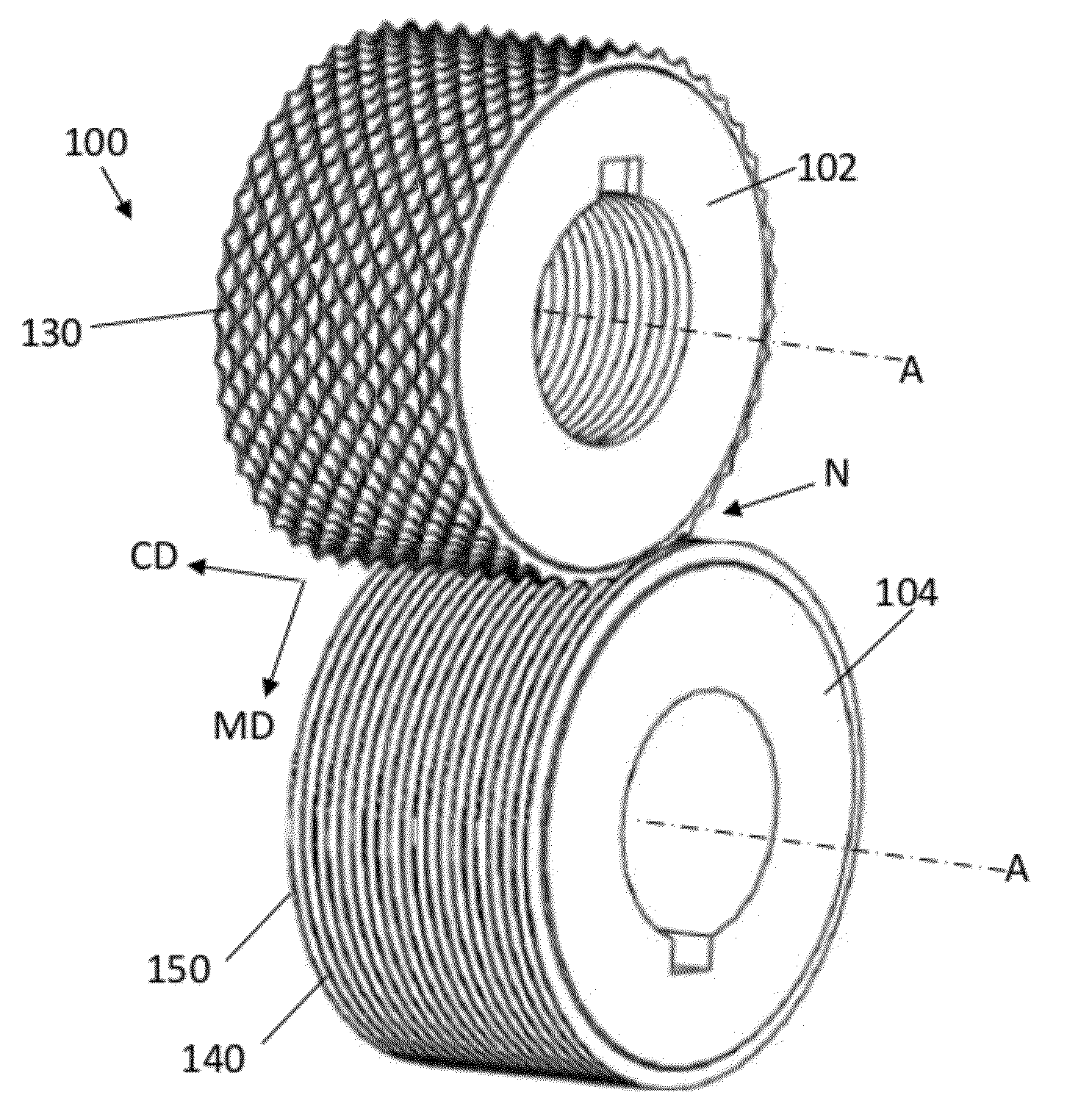
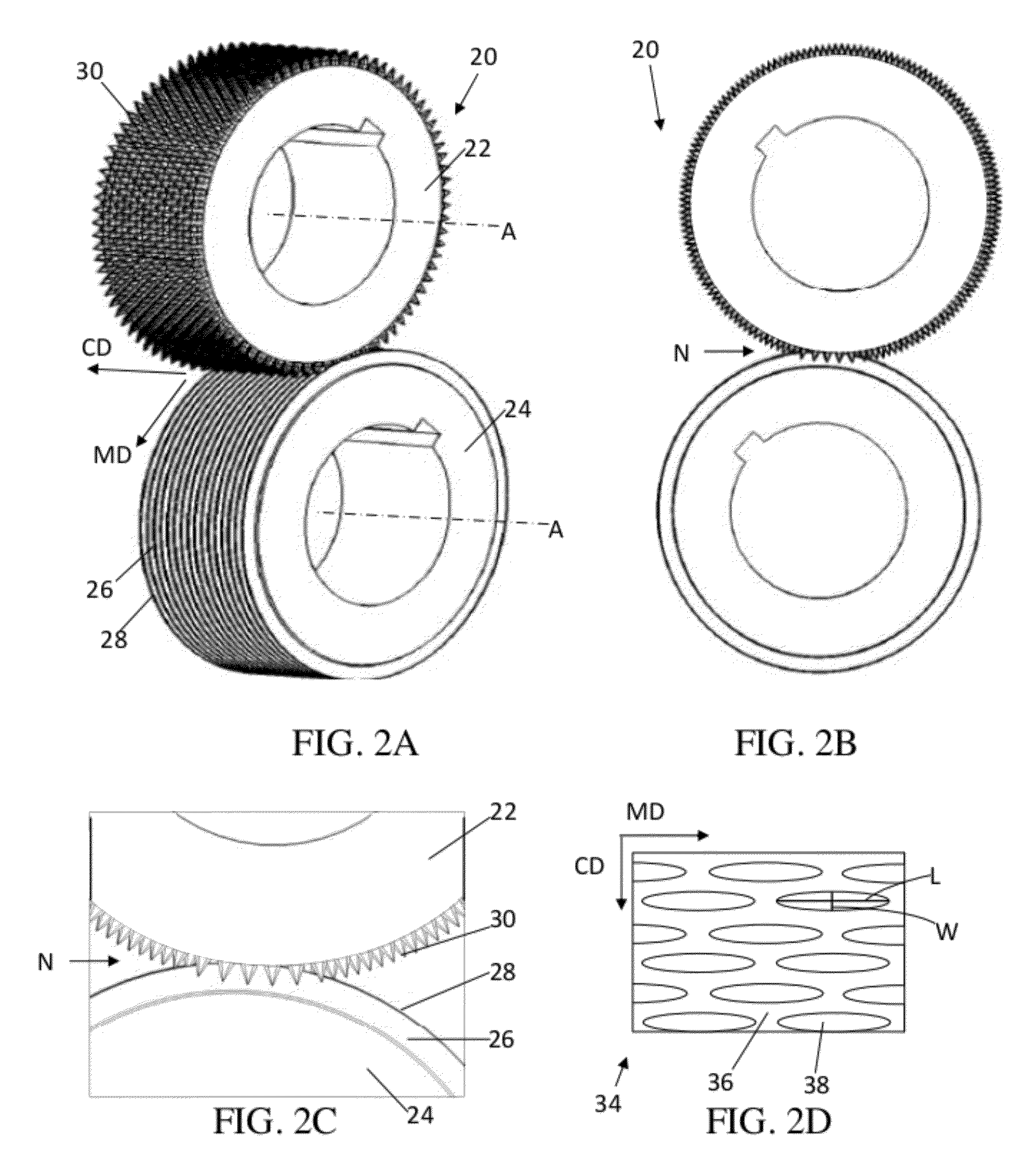
[0105]In one non-limiting example for making apertures in a polymer film, like the web 300 shown in FIG. 17 (comprising micro-apertures 312 and macro-apertures 314), an apparatus can be used that comprises a 1.5 mm pitch raised ridge RKA roll intermeshed with a 1.5 mm pitch ring roll at 3.8 mm depth of engagement. The raised ridge RKA roll has teeth that are oriented so the long direction runs in the MD. The teeth are arranged in a staggered pattern as shown in FIG. 5A. The teeth have a pyramidal shape with 6 sides that taper from the base to a sharp point at the tip, and have a height ht of 4.7 mm. The teeth have an included angle (α from FIG. 5B) of 62 degrees, a side wall angle on the long side of the tooth of about 6 degrees (β from FIG. 5C), and an end facet included angle of 90 degrees (γ from FIG. 5E). The ridges that span between the teeth on the RKA roll are non-radiused and form a flat surface. The teeth are finished at the ridge in a semi-truncated format as shown in FIG....

example 2

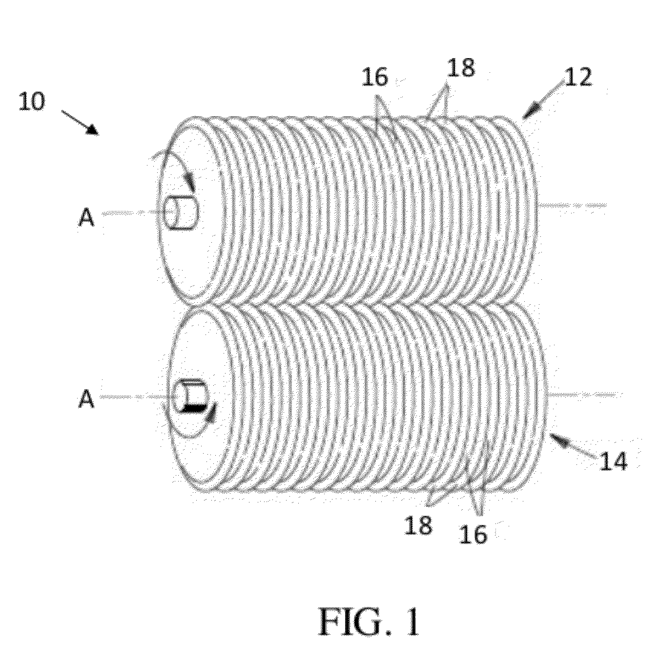
[0110]In one non-limiting example for making a corrugated web having apertures in the grooves, an apparatus can be used that comprises a 2.0 mm pitch raised ridge RKA roll intermeshed with a 2.0 mm pitch ring roll at 6.3 mm depth of engagement. The raised ridge RKA roll has teeth that are oriented so the long direction runs in the MD, and the ridges and grooves extend circumferentially around the ring roll. The teeth are arranged in a staggered pattern as shown in FIG. 5A. The teeth have a pyramidal shape with 4 sides that taper from the base to a sharp point at the tip, and have a height ht of 6.9 mm. The teeth have an included angle (α from FIG. 5B) of 57 degrees and a side wall angle on the long side of the tooth of about 5 degrees (β from FIG. 5C). The ridges that span between the teeth on the RKA roll are not rounded and form a flat surface. The teeth are finished at the ridge in the non-truncated format as shown in FIG. 6C. The teeth have an MD tooth spacing SMD tip to tip of ...


PUM

PropertyMeasurementUnit
depth of engagementaaaaaaaaaa
depthaaaaaaaaaa
distanceaaaaaaaaaa

Abstract

Apparatuses and processes for aperturing and stretching a web are disclosed. In one embodiment, the method involves feeding a web into a nip that is formed between at least one pair of intermeshing rolls. The first roll is a raised ridge rotary knife aperturing roll and the second roll is a ring roll; both rolls comprise ridges and grooves. The first roll comprises a plurality of spaced-apart teeth extending outwardly from the top surface of the ridges, said teeth having tips, wherein the top surface of said ridges are disposed between the tips of said teeth and the bottom surface of said grooves. These apparatuses and processes enable a web to be formed which comprises apertures having greater open area than previously achievable with traditional processes and apparatuses.

Description

CROSS REFERENCE TO RELATED APPLICATION[0001]This application is a continuation-in-part of application Ser. No. 13 / 094,195 which was filed on Apr. 26, 2011.FIELD OF THE INVENTION[0002]The present invention is directed to apertured web materials and apparatuses and methods for aperturing and stretching a web to create such materials.BACKGROUND OF THE INVENTION[0003]Various methods and apparatuses for aperturing, deforming, and / or stretching webs are disclosed in the patent literature. With an aperturing method such as rotary knife aperturing, it is difficult to produce a web having closely-spaced apertures wherein the apertures have desirable widths in the cross-machine direction (“CD”). In order to space aperture rows close together, activation teeth may be provided which have a very small included angle. However, this approach poses a problem because apertures are produced which do not have sufficient aperture width in the CD, even at high engagement depths (the interference of an a...

Claims


Application Information

Patent Timeline
Patent Type & Authority Applications(United States)
IPC IPC(8): B29C59/04B32B3/10
CPCB29C55/18B31F1/07B31F2201/0738Y10T428/24273B31F2201/0743B31F2201/0797B31F2201/0733A61F13/15577B29C43/226B29C53/22B29C53/265B29C53/285B29C55/08B29C59/04
Inventor COE, RICHARD GEORGEORR, JILL MARLENEGROSS, SARAH BETHISBURGH, ROBERT KARLKOCHER, LEROY JOSEPHMUHS, KEVIN GERARDMULLANE, TIMOTHY IAN
Owner THE PROCTER & GAMBLE COMPANY
Why Eureka
Try Eureka