Antenna testing system and antenna testing method

a technology of antenna testing and antenna, applied in the field of antenna testing technology, can solve the problem that the echo chamber cannot evaluate the corresponding communication performance, and achieve the effect of convenient and rapid test, convenient and fast implementation, and low cos

Inactive Publication Date: 2012-11-08
ZTE CORP
View PDF7 Cites 28 Cited by
  • Summary
  • Abstract
  • Description
  • Claims
  • Application Information

AI Technical Summary

Benefits of technology

[0020]In this disclosure, the simulation for transmission of wireless signals in real system is implemented by setting multiple test antennae in the anechoic chamber, and correspondingly setting signal transmitting components such as the base station simulator and the channel simulator. The wireless signals are transmitted to the DUT (mobile terminal) through the antennae in the anechoic chamber. Then, the DUT performs related decoding process according to the received wir...

Problems solved by technology

The traditional anechoic chamber cannot evaluate the corresponding communication performance of the OTA performance of the multi-antenna terminal.
Unfortunate...

Method used


Image

  • Antenna testing system and antenna testing method
  • Antenna testing system and antenna testing method

Examples


Embodiment Construction

[0022]In order to make the objective, the technical solution and the advantages of this disclosure more clear, this disclosure is described below in detail with reference to the drawings and embodiments.

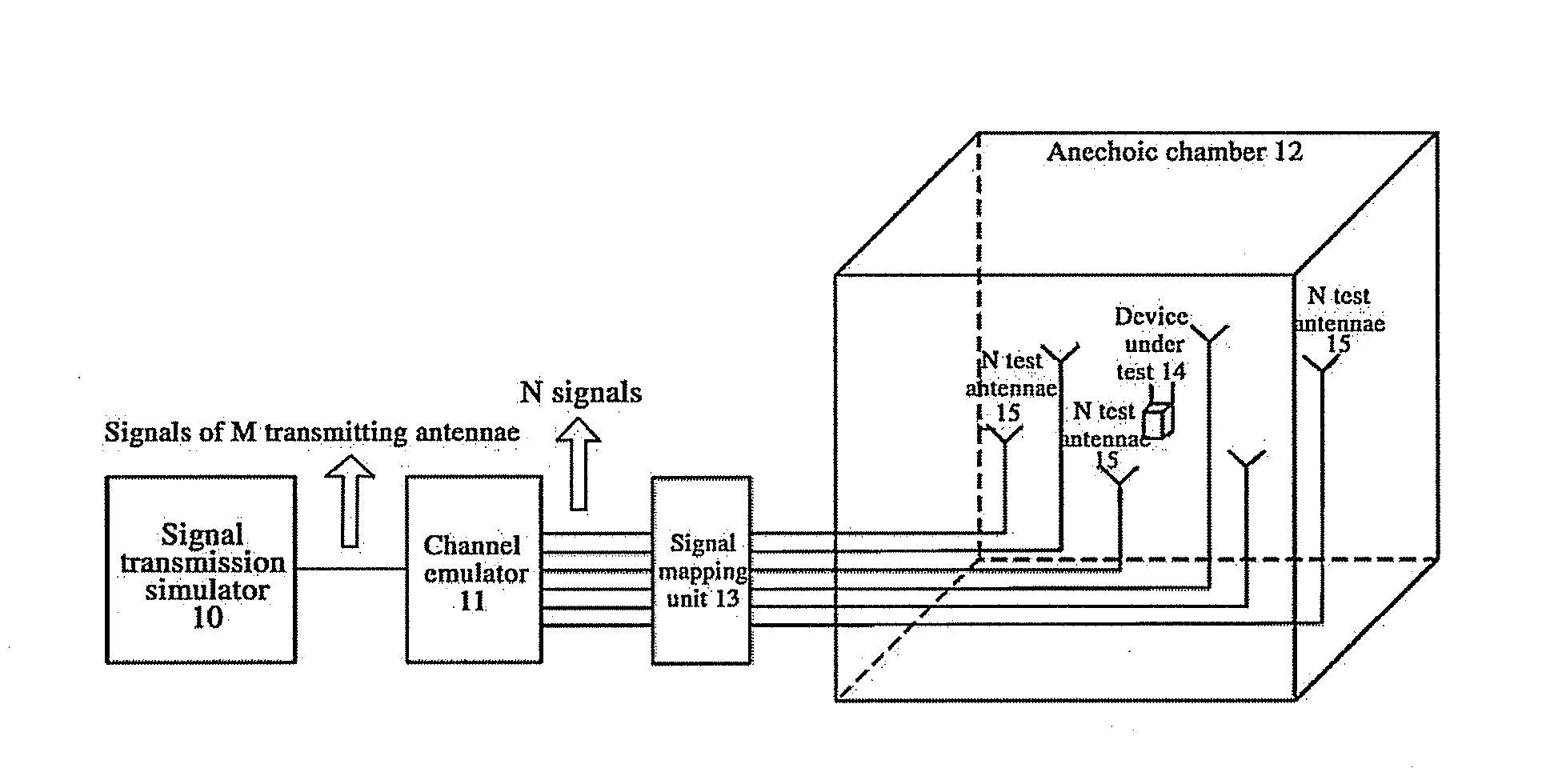
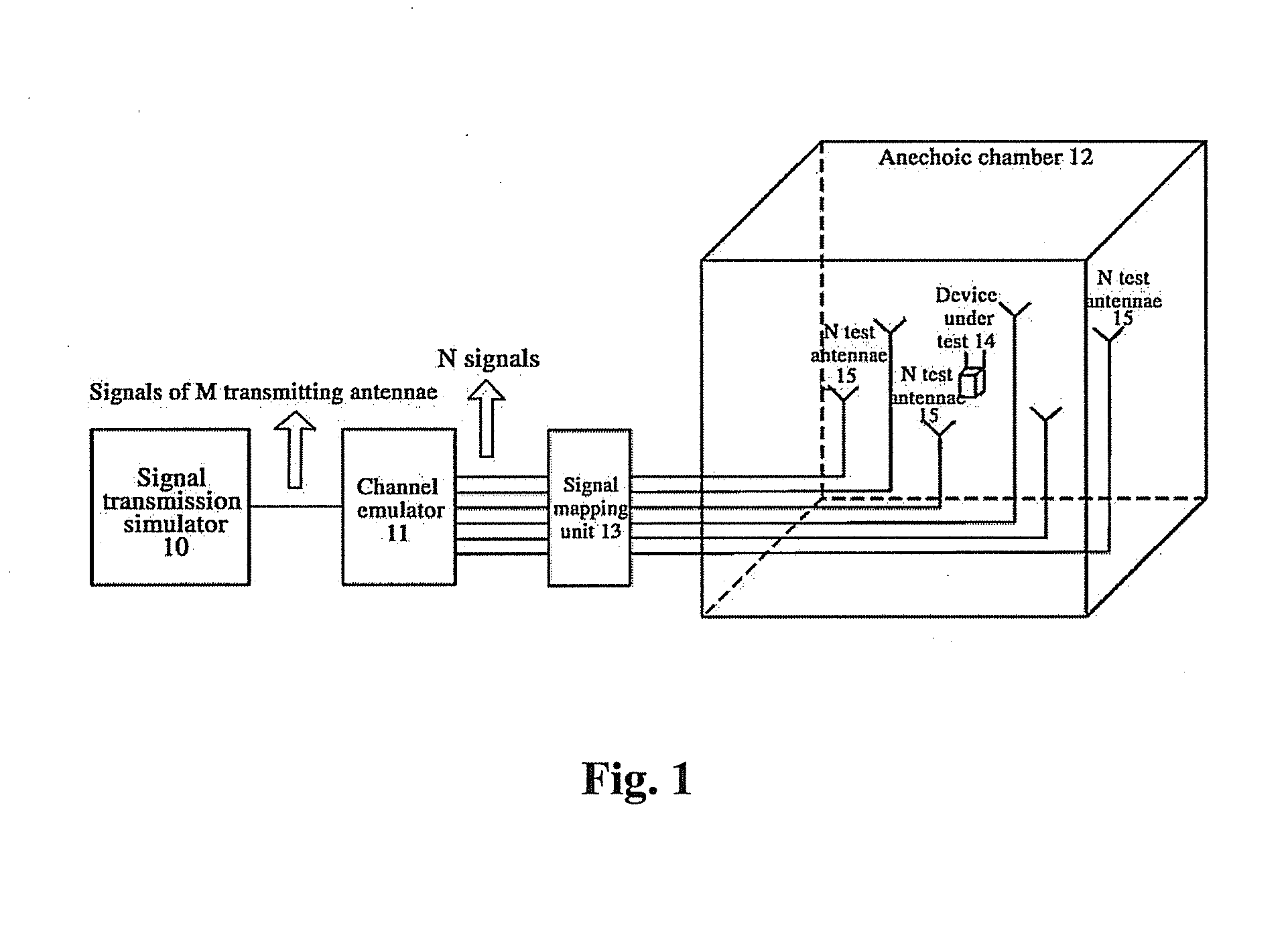
[0023]FIG. 1 shows a structural diagram of a testing system for a multi-antenna system of this disclosure. As shown in FIG. 1, the testing system for a multi-antenna system of this disclosure includes a signal transmission simulator 10, a channel emulator 11 and an anechoic chamber 12. The anechoic chamber 12 is equipped with more than two (N) antennae (test antennae) 15. Each antenna 15 is connected with the signal transmission simulator 10 through the channel emulator 11 to provide the wireless signals (transmitting signals) with the same number as the antennae for the DUT 14. The N test antennae 15 are located on the sphere of which center is the position where the DUT 14 is located. The best way for placing the test antennae 15 is that the test antennae 15 are located on the circ...


PUM


Abstract

This disclosure claims antenna testing system, including a signal transmission simulator, a channel emulator and an anechoic chamber; more than two antennae are set in the anechoic chamber; each antenna is connected with the signal transmission simulator through the channel emulator; the more than two antennae are located on the sphere which center is the position of the device under test. This disclosure claims an antenna testing method, comprising: more than one channel model for test is set in the signal transmission simulator; a channel model is selected from the more than one channel model; wireless signals are transmitted according to the selected channel model; after emulation processed by channel emulator, emulated wireless signals are transmitted through the antennae in anechoic chamber; DUT set in the anechoic chamber receives and then processes the signals transmitted from each antenna, and outputs the processing results.

Description

FIELD OF THE INVENTION[0001]This disclosure relates to the antenna testing technology, and in particular to an antenna testing system, and an antenna testing method based on the testing system.BACKGROUND OF THE INVENTION[0002]With the development of modern industry, various communication products can ensure the communication quality only by having excellent transmitting and receiving performance. The indexes of evaluating the transmitting and receiving performance include the Total Radiated Power (TRP), the Total Radiated Sensitivity (TRS), the space radio frequency (OTA, Over The Air), and so on. It is required that the TRP be greater than a set threshold, and the TRS be less than a set threshold, so that the corresponding requirement for communication can be met. When both the TRP and the TRS meet the set threshold, it means that the testing indexes are good.[0003]In order to ensure the normal use of mobile terminal device in network, the Cellular Telecommunications and Internet A...

Claims


Application Information

Patent Timeline
IPC IPC(8): H04B17/00
CPCH04B17/0082H04B7/04H04B17/391
Inventor GUO, YANGYU, ZHONG
Owner ZTE CORP
Why Eureka
Try Eureka