Surgical instrument, surgical handpiece and surgical drive system

a technology of surgical instruments and drive systems, applied in the field of surgical instruments, can solve the problems of increased temperature, inability to configure as small as desired, and mounting of the drive sha

Active Publication Date: 2012-11-08
AESCULAP AG
View PDF9 Cites 13 Cited by
  • Summary
  • Abstract
  • Description
  • Claims
  • Application Information

AI Technical Summary

Benefits of technology

[0010]In a third aspect of the invention, a surgical drive system comprises at least one surgical handpiece with a drive arranged in a housing and at least one of an open-loop and closed-loop control device for at least one of open-loop and closed-loop control of the drive. The system further comprises at least one surgical instrument. Said at least one surgical instrument comprises a shank and a drive shaft, which is rotatably mounted in the shank and bears or comprises a tool element at its distal end. In the distal end region of the shank a radial bearing is arranged or configured for the rotatable mounting of the drive shaft on the shank. The radial bearing is configured in the form of a needle bearing.

Problems solved by technology

A problem with such instruments is the mounting of the drive shaft.
However, these cannot be configured as small as desired.
Problems related to wear and increased rise in temperature are associated with this.

Method used


Image

  • Surgical instrument, surgical handpiece and surgical drive system
  • Surgical instrument, surgical handpiece and surgical drive system
  • Surgical instrument, surgical handpiece and surgical drive system

Examples


Embodiment Construction

[0034]Although the invention is illustrated and described herein with reference to specific embodiments, the invention is not intended to be limited to the details shown. Rather, various modifications may be made in the details within the scope and range of equivalents of the claims and without departing from the invention.

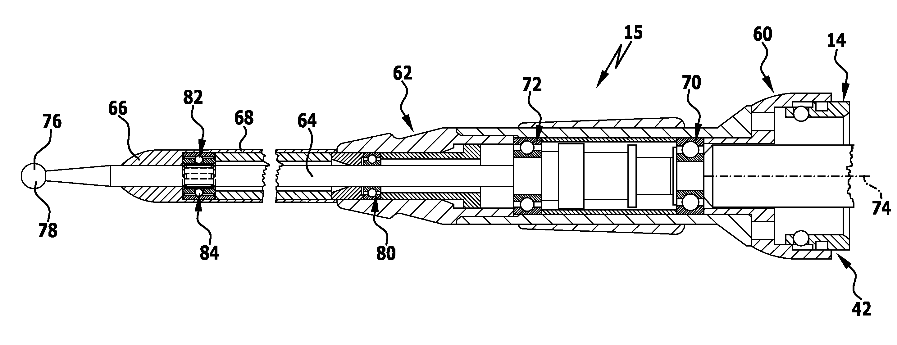
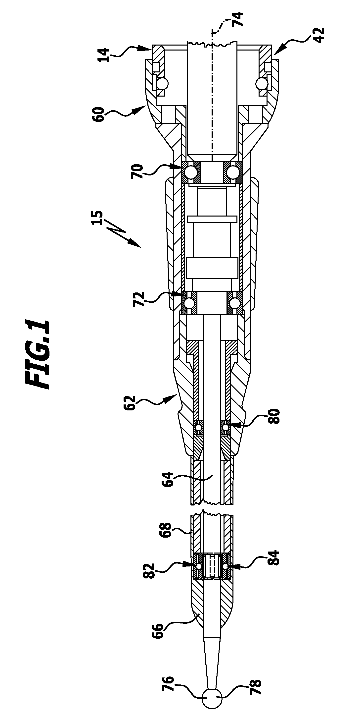
[0035]Needle bearings have a significantly higher load capacity compared to ball bearings and can therefore absorb significantly higher forces without being damaged thereby. The needle bearing preferably forms the distal-most radial bearing on the shank, which does not have to absorb any axial forces. Needle bearings cannot absorb any axial forces and therefore needle bearings are excellently suited as radial bearings at this location of the shank. Overall, with the same size, i.e. the same outside diameter, needle bearings can absorb significantly higher forces than ball bearings. In other words, the same forces can be absorbed with needle bearings that have a si...


PUM


Abstract

In order to improve a surgical instrument comprising a shank and a drive shaft, which is rotatably mounted in the shank and bears or comprises a tool element at its distal end, wherein in the distal end region of the shank a radial bearing is arranged or configured for the rotatable mounting of the drive shaft on the shank, such that a reliable operation is possible even with increasing miniaturisation of the shanks, it is proposed that the radial bearing is configured in the form of a needle bearing.
An improved surgical handpiece as well as an improved surgical drive system are additionally proposed.

Description

CROSS-REFERENCE TO RELATED APPLICATIONS[0001]This application claims the benefit of German Patent Application No. 10 2011 050 193.2 filed on May 6, 2011.[0002]The present disclosure relates to the subject matter disclosed in German patent application number 10 2011 050 193.2, filed May 6, 2011, which is incorporated by reference herein in its entirety and for all purposes.FIELD OF THE INVENTION[0003]The present invention relates to surgical instruments generally, and more specifically to a surgical instrument comprising a shank and a drive shaft, which is rotatably mounted in the shank and bears or comprises a tool element at its distal end, wherein in the distal end region of the shank a radial bearing is arranged or configured for the rotatable mounting of the drive shaft on the shank.[0004]The present invention additionally relates to surgical handpieces generally, and more specifically to a surgical handpiece comprising a drive arranged in a housing.[0005]And finally, the invent...

Claims


Application Information

Patent Timeline
Patent Type & Authority Applications(United States)
IPC IPC(8): A61B17/00
CPCF16C19/46F16C19/49F16C33/4652A61B17/1613F16C33/4605F16C2316/10
Inventor BLUST, EDGAR
Owner AESCULAP AG
Why Eureka
Try Eureka