
Camera calibration using an easily produced 3D calibration pattern

Active Publication Date: 2012-11-15
INTEL CORP
View PDF4 Cites 36 Cited by
  • Summary
  • Abstract
  • Description
  • Claims
  • Application Information

AI Technical Summary

Problems solved by technology

However, 3D calibration targets typically require great manufacturing accuracy to place the target fiducials at precise locations, resulting in a high cost.
Detecting the target features can also be more difficult on a 3D target.

Method used


Image

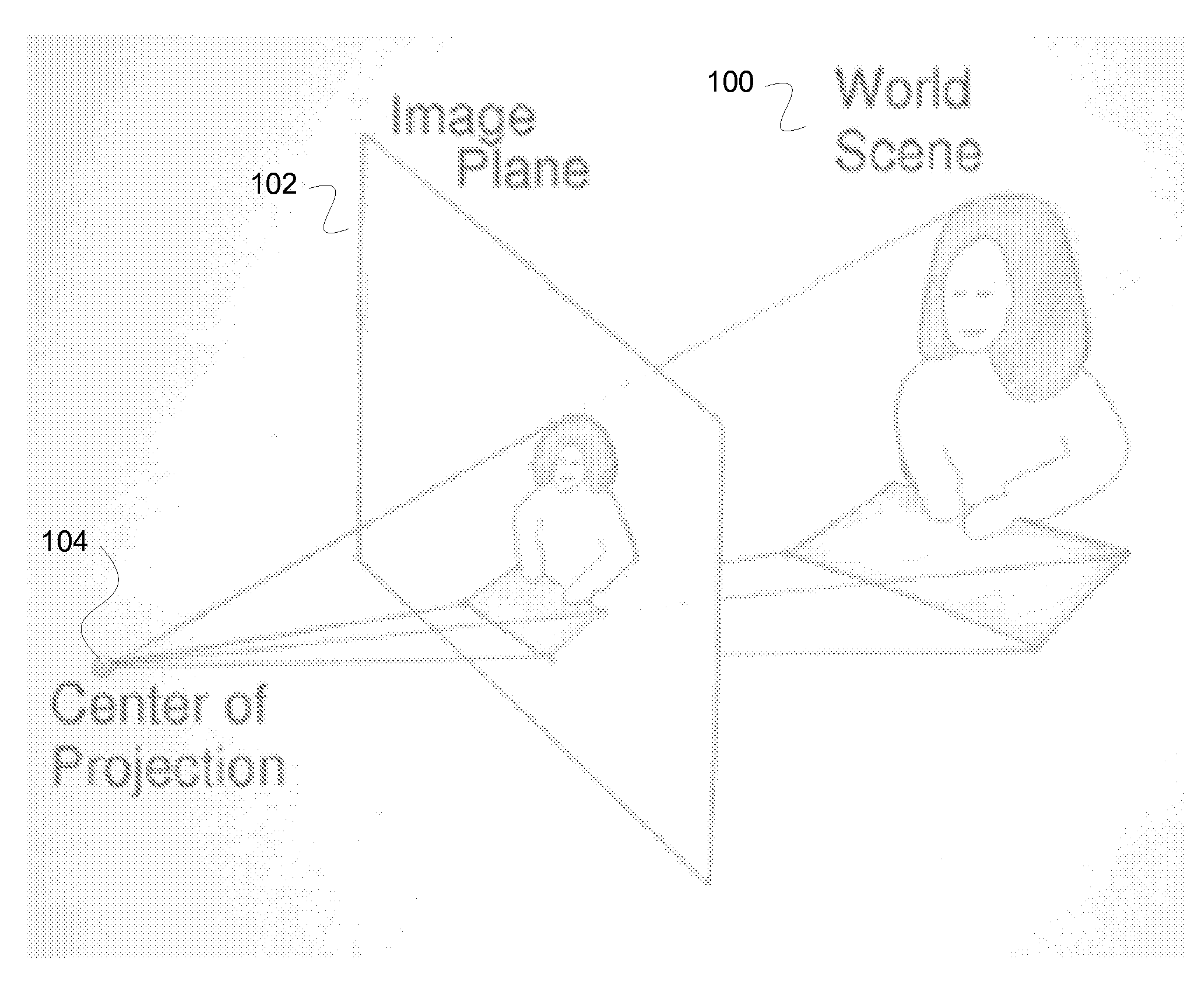
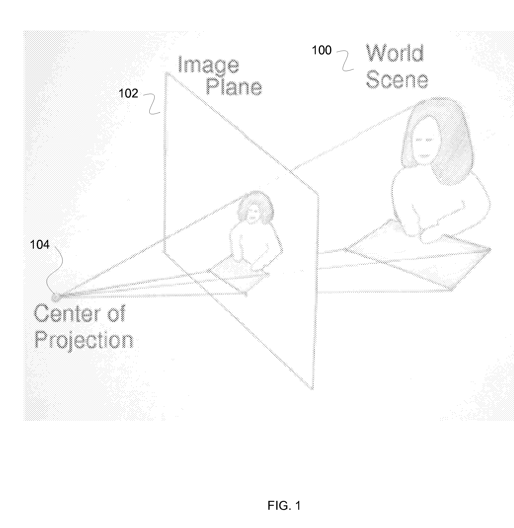
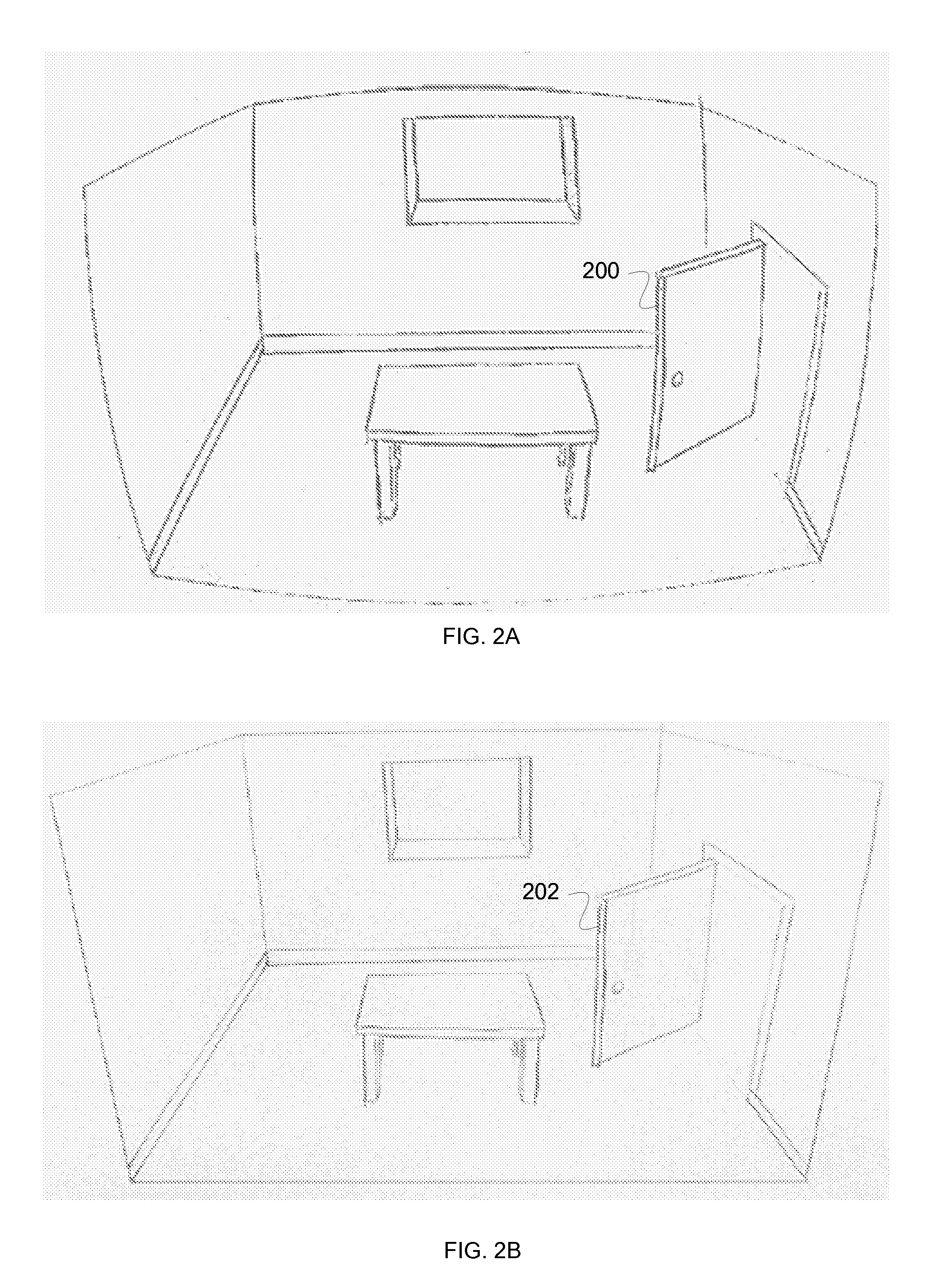
  • Camera calibration using an easily produced 3D calibration pattern
  • Camera calibration using an easily produced 3D calibration pattern
  • Camera calibration using an easily produced 3D calibration pattern

Examples


Embodiment Construction

[0034]The invention can be implemented in numerous ways, including as a process; an apparatus; a system; a composition of matter; a computer program product embodied on a computer readable storage medium; and / or a processor, such as a processor configured to execute instructions stored on and / or provided by a memory coupled to the processor. In this specification, these implementations, or any other form that the invention may take, may be referred to as techniques. The order of some steps of disclosed processes may be altered within the scope of the invention. Unless stated otherwise, a component such as a processor or a memory described as being configured to perform a task may be implemented as a general component that is temporarily configured to perform the task at a given time or a specific component that is manufactured to perform the task. As used herein, the term ‘processor’ refers to one or more devices, circuits, and / or processing cores configured to process data, such as...


PUM


Abstract

A system for computing one or more calibration parameters of a camera is disclosed. The system comprises a processor and a memory. The processor is configured to provide a first object either marked with or displaying three or more fiducial points. The fiducial points have known 3D positions in a first object reference frame. The processor is further configured to provide a second object either marked with or displaying three or more fiducial points. The fiducial points had known 3D positions in a second object reference frame. The processor is further configured to place the first object and the second object in a fixed position such that the fiducial point positions of the first and second objects are non-planar. The processor is further configured to compute one or more calibration parameters of the second camera using computations based on images taken of the fiducials.

Description

BACKGROUND OF THE INVENTION[0001]Camera calibration is a critical step in a large variety of image processing applications. Most products which involve one or more cameras and perform image processing or analysis require a camera calibration step during manufacturing. It is desirable to be able to calibrate the camera accurately, as quickly as possible, while also requiring as small an area on the manufacturing floor as possible.[0002]In traditional camera calibration methods, the camera(s) views a calibration target from one or more different positions. Calibration targets are rigid objects that contain known visual patterns that are possible to locate with great accuracy in images. Some approaches require the camera to view a planar, or two dimensional (2D), calibration target from many (four or more) different positions and distances. The planar target is often created by printing a pattern on a high resolution printer and then mounting it to a flat surface. The target contains f...

Claims


Application Information

Patent Timeline
IPC IPC(8): H04N13/02
CPCG06T7/0018G06T2207/10004G06T2207/30208G06T2207/30244G06T2207/10016G06T2207/30204G06T7/80
Inventor GROSSMANN, ETIENNEWOODFILL, JOHN ISELINGORDON, GAILE GIBSON
Owner INTEL CORP
Learn More