Thermocouple assembly with guarded thermocouple junction

a technology of thermocouple junction and thermocouple assembly, which is applied in the direction of thermoelectric devices, instruments, heat measurement, etc., can solve the problems of affecting the uniformity of the resulting structure on the surface of the substrate, shortened the lifetime of the thermocouple, and unusable areas on the surface of the finished substra

Active Publication Date: 2013-02-26
ASM IP HLDG BV
View PDF147 Cites 211 Cited by
  • Summary
  • Abstract
  • Description
  • Claims
  • Application Information

AI Technical Summary

Problems solved by technology

If the temperature varies greatly across the surface of the substrate, the deposited layer could be uneven or have defects which may result in unusable areas on the surface of the finished substrate.
Similarly, non-uniformity or instability of temperatures across a substrate during other thermal treatments can affect the uniformity of resulting structures on the surface of the substrate.
Typical issues that relate to shortened thermocouple lifetime include broken wires and inconsistent temperature measurement.
The inconsistent temperature measurement of thermocouples may result from an inconsistent location of the junction of the wires (i.e., thermocouple junction) relative to the measuring tip of the sheath.
One example of when a thermocouple is considered to have failed is when the temperature measured is not accurate or is inconsistent from measurement to measurement.
The reaction chamber must subsequently be shut down so that the failed thermocouple can be removed, and the tool down-time decreases profitability and increases cost of ownership of the tool.

Method used


Image

  • Thermocouple assembly with guarded thermocouple junction
  • Thermocouple assembly with guarded thermocouple junction
  • Thermocouple assembly with guarded thermocouple junction

Examples


Embodiment Construction

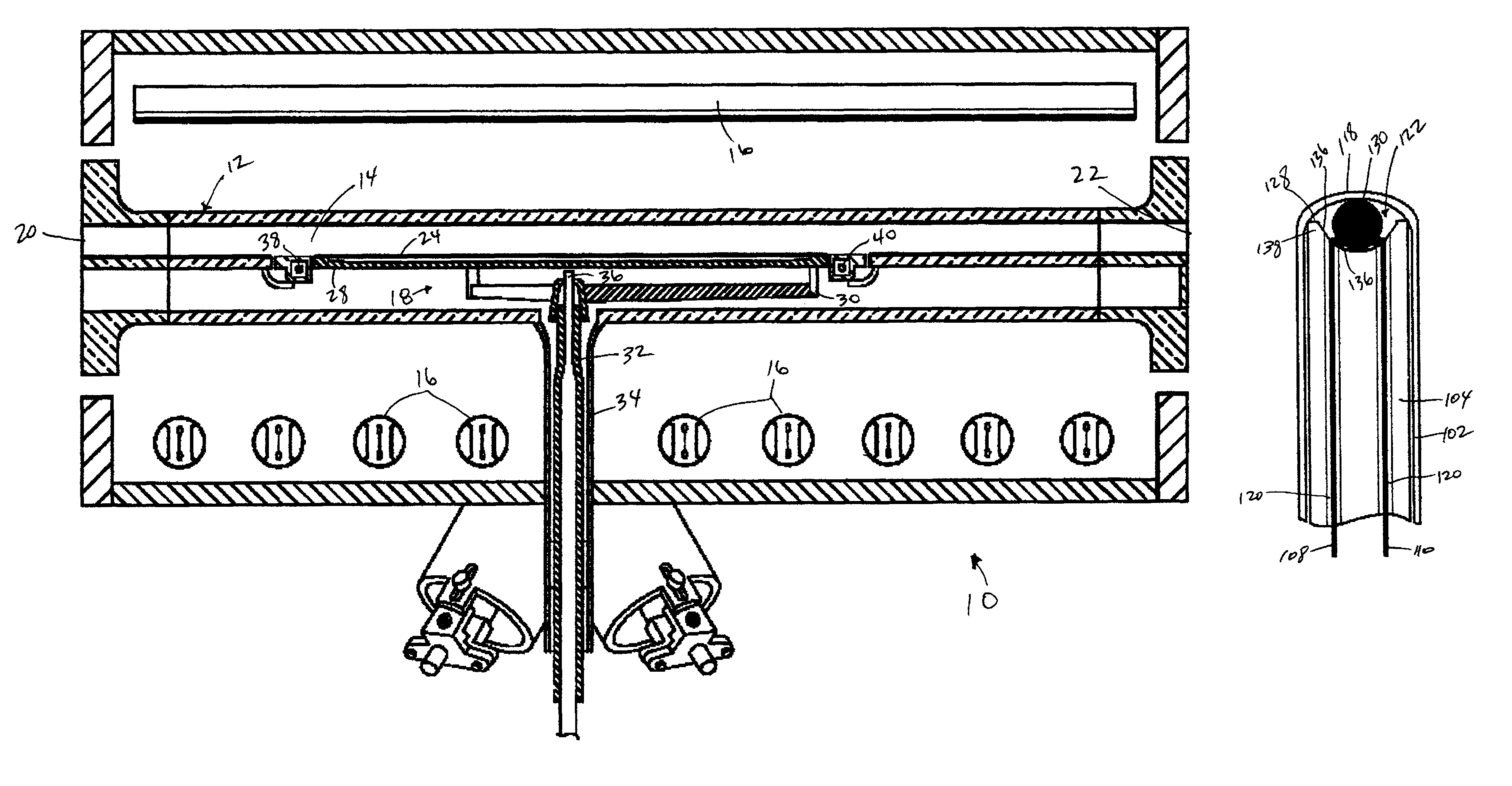
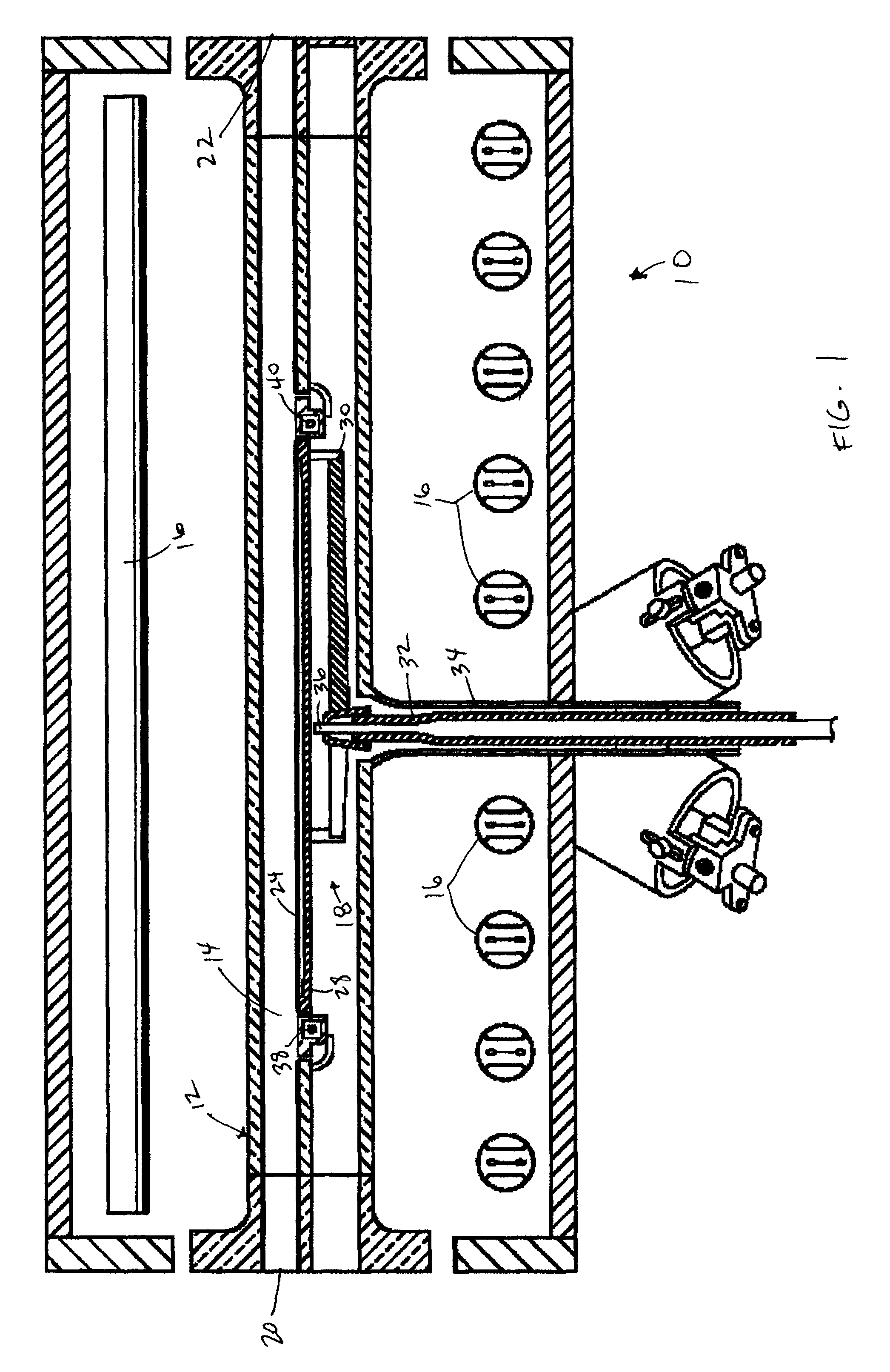
[0021]Referring to FIG. 1, an exemplary embodiment of a chemical vapor deposition (“CVD”) reactor 10 for processing semiconductor substrates is shown. While the illustrated embodiment is a single substrate, horizontal flow, cold-wall reactor, it should be understood by one skilled in the art that the thermocouple concept described herein may be used in other types of semiconductor processing reactors as well as other non-semiconductor processing applications that require accurate temperature sensors. The CVD reactor 10 includes a reaction chamber 12 defining a reaction space 14, heating elements 16 located on opposing sides of the reaction chamber 12, and a substrate support mechanism 18. The reaction chamber 12 is an elongated member having an inlet 20 for introducing reactant gases into the reaction space 14 and an outlet 22 through which the reactant gases and process by-products exit the reaction space 14. In an embodiment, the reaction chamber 12 is formed of transparent quartz...


PUM

PropertyMeasurementUnit
distanceaaaaaaaaaa
distanceaaaaaaaaaa
distanceaaaaaaaaaa

Abstract

An improved thermocouple assembly for providing a temperature measurement is provided. The thermocouple assembly includes a sheath having a measuring tip, a support member received within the sheath, and first and second wires disposed within the support member. An end of each of the first and second wires are fused together to form a thermocouple junction therebetween. A recessed region is formed in a distal end of the support member, and the thermocouple junction is fixedly located at the base of the recessed region such that the recessed region maintains the thermocouple junction in a substantially fixed position relative to the measuring tip of the sheath.

Description

FIELD OF THE INVENTION[0001]The present invention relates to temperature measuring devices, and more particularly, this invention relates to a thermocouple assembly for use in semiconductor processing.BACKGROUND OF THE INVENTION[0002]Semiconductor processing chambers are used for depositing various material layers onto a substrate surface or surfaces. The processing chambers can be used for low-temperature processing, high-temperature processing, or a combination of both high- and low-temperature processing. One or more substrates or workpieces, such as silicon wafers, are placed on a workpiece support within the processing chamber. Both the substrate and workpiece support are heated to a desired temperature. In a typical chemical vapor deposition (“CVD”) processing step, reactant gases are passed over each heated substrate, whereby a CVD reaction deposits a thin layer of the reactant material in the reactant gases on the substrate surface(s). The processing may also include atomic ...

Claims


Application Information

Patent Timeline
Patent Type & Authority Patents(United States)
IPC IPC(8): G01K7/02H01L35/04G01K1/14
CPCG01K7/04G01K7/02
Inventor AGGARWAL, RAVINDER K.HARO, ROBERT C.
Owner ASM IP HLDG BV
Why Eureka
Try Eureka