Modular thermoelectric couple and stack

a thermoelectric couple and module technology, applied in the field of thermoelectric heat pumps, can solve the problems of reducing overall cooling efficiency, reducing operating efficiency, and high cumulative heat resistance or impedance loss, and achieve the effect of reducing undesirable thermal impedance loss during system operation

Inactive Publication Date: 2005-02-15
FEHER STEVE
View PDF6 Cites 92 Cited by
  • Summary
  • Abstract
  • Description
  • Claims
  • Application Information

AI Technical Summary

Benefits of technology

It is a primary object and aim of this invention to provide a thermoelectric semiconductor module of improved character having an optimally minimal number of component parts that can produce undesirable thermal impedance losses during system operation.
A further object is the provision of improved thermoelectric modules and assembly thereof of reduced expansion and contraction problems between the component parts of the “hot” and “cold” sections.

Problems solved by technology

All known Peltier modular constructions have one or more of the following undesirable properties requiring compensation: an excessively high heat on a thermoelectric element “hot” side that can increase the temperature of the “cold” side impermissibly thereby reducing overall cooling efficiency; module packaging consisting of many different parts that results in correspondingly high cumulative heat resistance or impedance losses and reduction of operating efficiency (COP); overall relatively high weight; many interconnected metal (e.g., copper) and ceramic parts whose coefficients of expansion conflict thereby limiting size and numbers of modules that can be efficiently and reliably used in a unit.

Method used


Image

  • Modular thermoelectric couple and stack
  • Modular thermoelectric couple and stack
  • Modular thermoelectric couple and stack

Examples


first embodiment

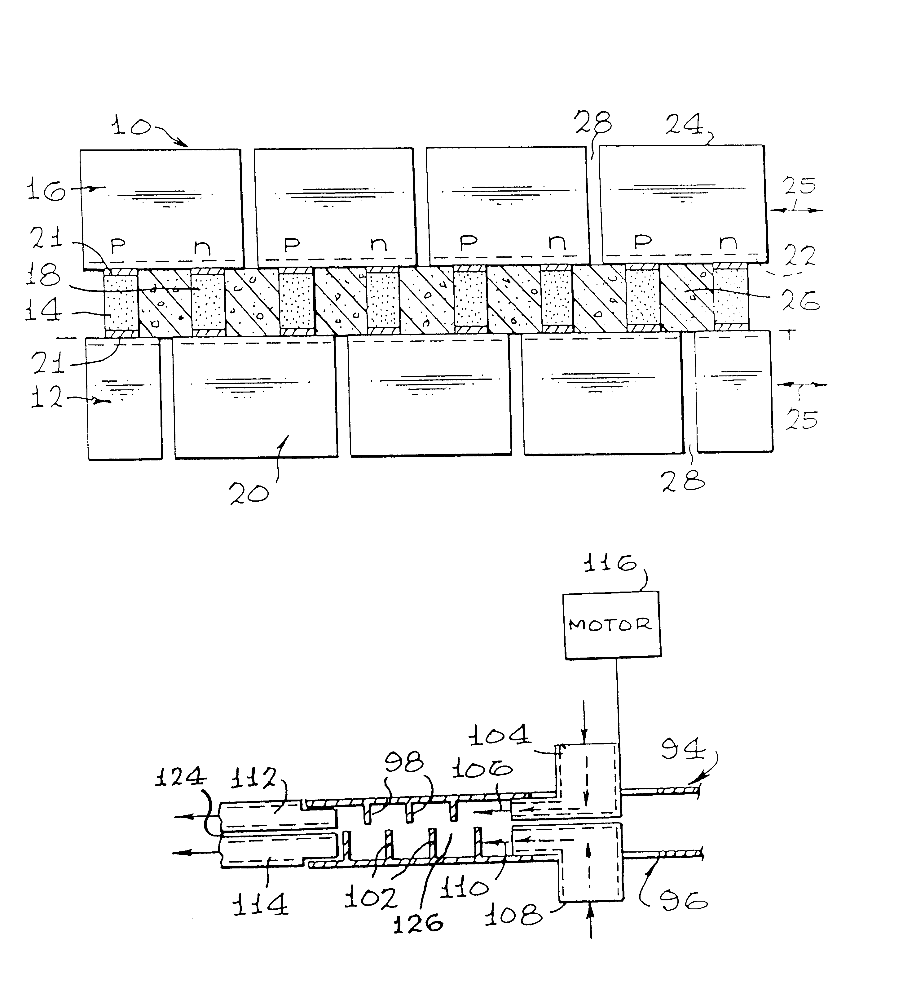
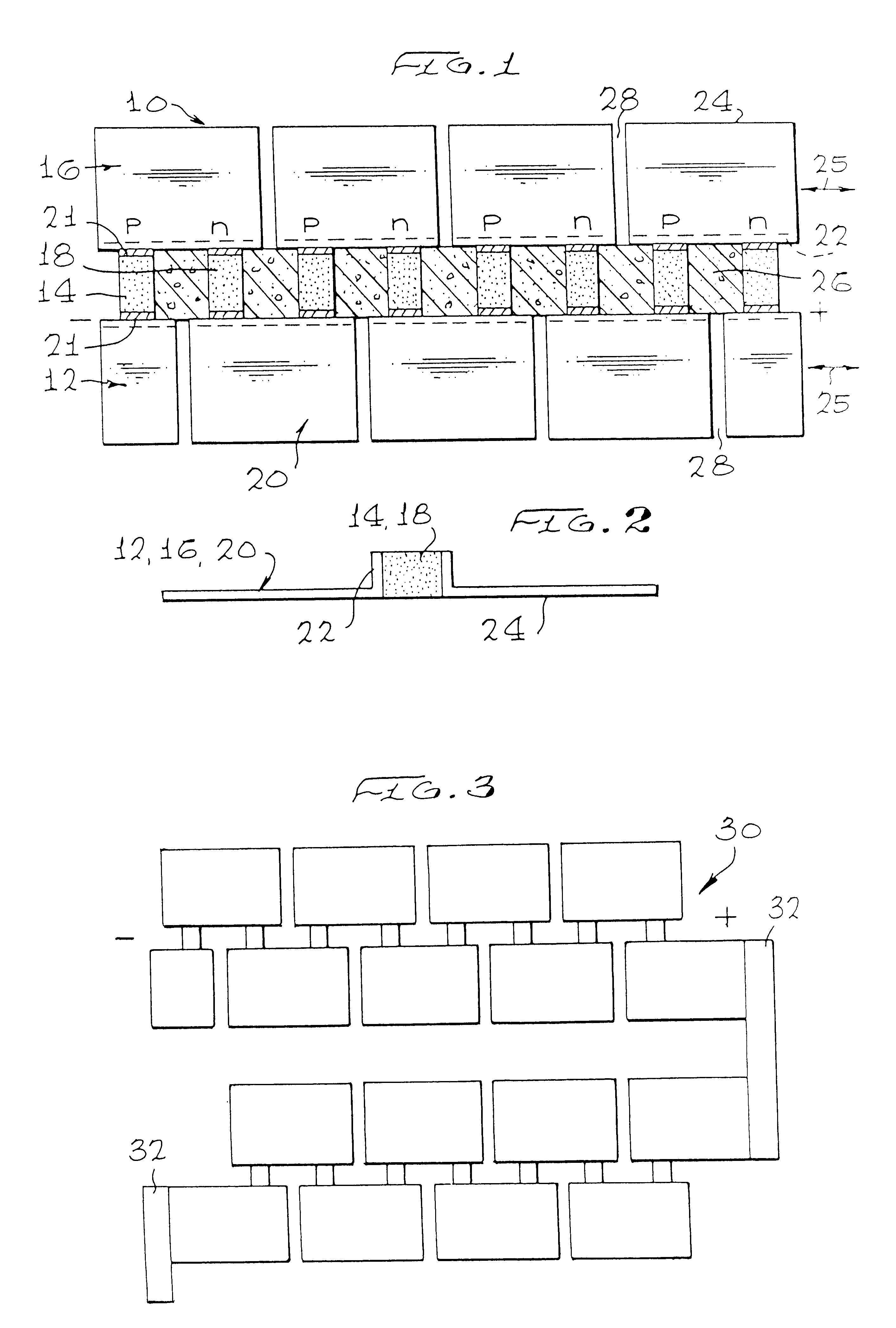
Turning now to the drawing and the invention, reference is made primarily to FIGS. 1 and 2. As shown there, a thermoelectric semiconductor couple of the invention is enumerated generally as 10 and includes a first electrode and heat transferring means 12, a quantity of a p-type the thermoelectric semiconductor 14, a second electrode and heat transferring means 16, a quantity of an n-type thermoelectric semiconductor 18 and a third electrode and heat transferring means 20. Each of the electrodes and heat transferring means, as the name implies, is constructed of a good electrical conductor as well as a suitable material for this purpose is a metal such as copper or aluminum. As indicated by the symbols “+” and “−”, the means 12, 16 and 20 when connected with the semiconductor quantities 14 and 18 form an electrical series circuit via which the semiconductor quantities are energized to function thermoelectrically as a heat pump. The order of the p-type and n-type semiconductors may be...

third embodiment

For the ensuing description of the invention, reference is made to FIG. 7. This embodiment is especially advantageous in being able to be assembled directly onto a solid surface which may be either part of an object to be “cooled”, for example, or a waste heat sink. As shown, four electrodes and heat transferring means 44, 46, 48 and 50 have four pairs of p-type and n-type thermoelectric semiconductor bodies or pellets 52 and 54, respectively secured thereto as in the first described embodiment. However, instead of a further set of electrodes and heat transferring means, pairs of p- and n-type semiconductors are serially electrically connected by a conductor 56 deposited on one surface of a dielectric segment 58 (e.g., ceramic), the opposite surface of which can be adhered in any desired manner (e.g., soldered) to any desired solid surface without interfering with the electric energization of the pellets.

FIG. 8 shows a prior art semiconductor module 60 composed of a number of differ...

fifth embodiment

For the ensuing detailed description of the invention reference is now made to FIGS. 14-16. First and second support plates 128 and 130, which may be of identical construction, include sets 132 of parallel slotted openings 134 of such relative spaced apart relation as to receive previously described fin / conductors 36, 38 therethrough with the plates pressed against the module conductors. When so assembled, the plates 128 and 130 provide overall structural rigidity to the modules while, at the same time, establishing an air barrier between the “hot” and “cold” sides of the modules that limits convection into the space between the two plates.

In addition, it is preferable to provide an edge seal 136 such as an O-ring, for example, to reduce even further external convection air currents from moving into the space between the plates and into contact with the semiconductor pellets degrading system heat efficiency. This seal also prevents humid ambient air from making its way to the thermo...


PUM


Abstract

A thermoelectric semiconductor module (10) includes a plurality of semiconductor pellets (14, 18) having Peltier characteristics are mechanically interconnected and arranged in an electrical series circuit with heat transferring means (12, 16, 20) with all interconnections being directly made. The means (12, 16, 20) can be of platelike construction with an L-shaped cross-section or, alternatively, with a U-shaped cross-section. A large number of modules (10) can be arranged in a two-dimensional or three-dimensional stack (30) with adjacent lines or planes of modules electrically interrelated by end segment connectors (32). In a further version, one side of a modular plane has heat exchanger fins (44-50) while the other side is electrically connected by ceramic segments (58) with deposited conductors (56). In yet another version, the modules are mounted onto rotating discs (94, 96) so as to act as a fluid impeller moving therepast enhancing thermal efficiency.

Description

BACKGROUND1. Background of the InventionThe present invention relates generally to a thermoelectric heat pump, and, more particularly, to such a heat pump constructed of thermoelectric modules arranged in a stack.2. Description of Related ArtIt is known that when a quantity of p-type thermoelectric material is serially interconnected with a quantity of n-type thermoelectric material, that on passing an electric current through the so-formed module that heat will either be absorbed or emitted depending upon the current direction, thus acting as a heat pump as a result of what is known as the Peltier effect. It is also known to construct a relatively large refrigeration panel from a large number of semiconductor elements unitarily arranged. U.S. Re. No. 35,441. THERMOELECTRIC SEMICONDUCTOR HAVING A POROUS STRUCTURE DEAERATED IN A VACUUM AND THERMOELECTRIC PANEL USING P-TYPE AND N-TYPE THERMOELECTRIC SEMICONDUCTORS. Still further, U.S. Pat. No. 5,841,064, PELTIER MODULE, discloses a mo...

Claims


Application Information

Patent Timeline
Patent Type & Authority Patents(United States)
IPC IPC(8): H01L35/32H01L35/28H01L35/30H01L23/38H02N11/00
CPCH01L35/32H01L35/30H10N10/17H10N10/13
Inventor FEHER, STEVE
Owner FEHER STEVE
Why Eureka
Try Eureka