Textured surfaces for breast implants

Active Publication Date: 2017-02-23
ESTAB LABS
View PDF8 Cites 18 Cited by
  • Summary
  • Abstract
  • Description
  • Claims
  • Application Information

AI Technical Summary

Benefits of technology

[0028]There is also a desire for methods that can produce such top

Problems solved by technology

Fibrous capsule formation around soft tissue body implants remains a persistent problem for many patients following prosthesis implantation.
Silicone shell breast implants are particularly troublesome with potential development of capsular contracture, which is considered to be one of the primary reasons for device failure.
The pathoetiology of capsular contracture formation around silicone mammary implants is both complex and enigmatic, however; it is thought to be an over-exaggeration of the normal foreign body reaction.
There are a number of known risk factors for its development such as implantation post-radiotherapy and bacterial infection around the implant.
The latter hypothesis, however, neglects to consider the initial reaction of the body to the implant and instead focuses on attempting to firmly integrate the implant within the breast so that the movement of the prosthesis is minimized; potentially leading to reduced contracture.
Furthermore, once capsular contracture has occurred around a textured implant, surgical removal proves much more traumatic and can result in the unnecessary loss of the surrounding breast tissue as there is excessive tissue ingrowth into the more heavily textured implant (the so called “velcro effect”).
The basic design and fabrication of current commercially available breast implants was generally conceived in the 1960's with limited scientific consideration or evaluation in particular due to the available scientific know-how and technology at the time.
However, as explained below there has been a great degree of difficulty in identifying key surface feature(s) that affect the cellular response upon implantation.
The roughness scale to which cells are most responsive is, however, quite complex.
As a result, the surface features that might be important for providing desirable cell responses in a given environment have been difficult to identify.
However, due to health concerns, use of polyurethane was eventually superseded by silicone as the polymer material of choice due to silicone's biologically benign nature and its FDA approval as discussed above.
In this regard, implant surfaces that are “smooth” do in fact usually exhibit an unintentional minor degree of surface roughness as a result of fine ripples, grooves and/or other surface anomalies that are an inherent bi-product of the process by which the surfaces are prepared (for instance forming during the curing process as the liquid silicone trickles down the mandrel under force of gravity).
However, whilst conventional photolithographic techniques can provide simple geometric structures such as the grooves depicted in WO2009/046425, such methods are not attractive when more complex geometric patterns are sought (e.g. spheres, wedges) sinc

Method used


Image

  • Textured surfaces for breast implants
  • Textured surfaces for breast implants
  • Textured surfaces for breast implants

Examples


example 1

Production of ADM BM PDMS F—Fabricated Implant Surface by Grayscale Lithography of Acellular (Decellularised) Dermal Matrix Pattern and Reproduction in Silicon by Modified Deep Reactive Ion Etching (DRIE) to Create a Template Before Creating Stamps of ADM BM Pattern in PDMS

Imaging the ADM BM Surface

[0458]The basement membrane (BM) side of the ADM BM surface is distinguished from dermal side through visually checking the tissue for roughness and a buff-colour. Further, BM characteristically repels water and the contact angle of the water is higher than on BM side than PD side. The samples were then placed BM side up onto microscope slides and allowed to slowly air dry at 4° C. for 24 hours. Over one hundred 90 μm×90 μm2 AFM scans were conducted in different areas of the ADM sample, on a number of different samples.

Preparing an Electronic File From Height Information of Grayscale AFM Images

[0459]The raw images from the AFM database were loaded into the following scanning probe analysi...

example 2

Creation of ADM BM C—Casting of Acellular Dermal Matrix in PDMS

Preparation of Acellular Dermal Matrix (ADM)

[0464]ADM washed in sterile deionised water×3 and attached BM side up onto microscope slide and allowed to slowly air dry for 24 hours at 4° C. Basement membrane (BM) side of ADM is distinguished from dermal side through visually checking the tissue for roughness and a buff-colour. Further, BM characteristically repels water and the contact angle of the water is higher than on BM side than RD side.

Silanization

[0465]To allow easy peeling of PDMS from ADM BM, the ADM was silanized. Silanization performed by placing ADM in vacuum desiccator on a steel-meshed platform with 100 ul of the fluorosilane TMCS in a 3 cm diameter petri dish beneath the ADM. The vacuum was pumped for 30 seconds-1 min until the TMCS is visibly beginning to bubble and evaporate. At this stage the desiccator is held under vacuum for 10 minutes to allow the TMCS to silanize the ADM surface. The ADM is then rea...

example

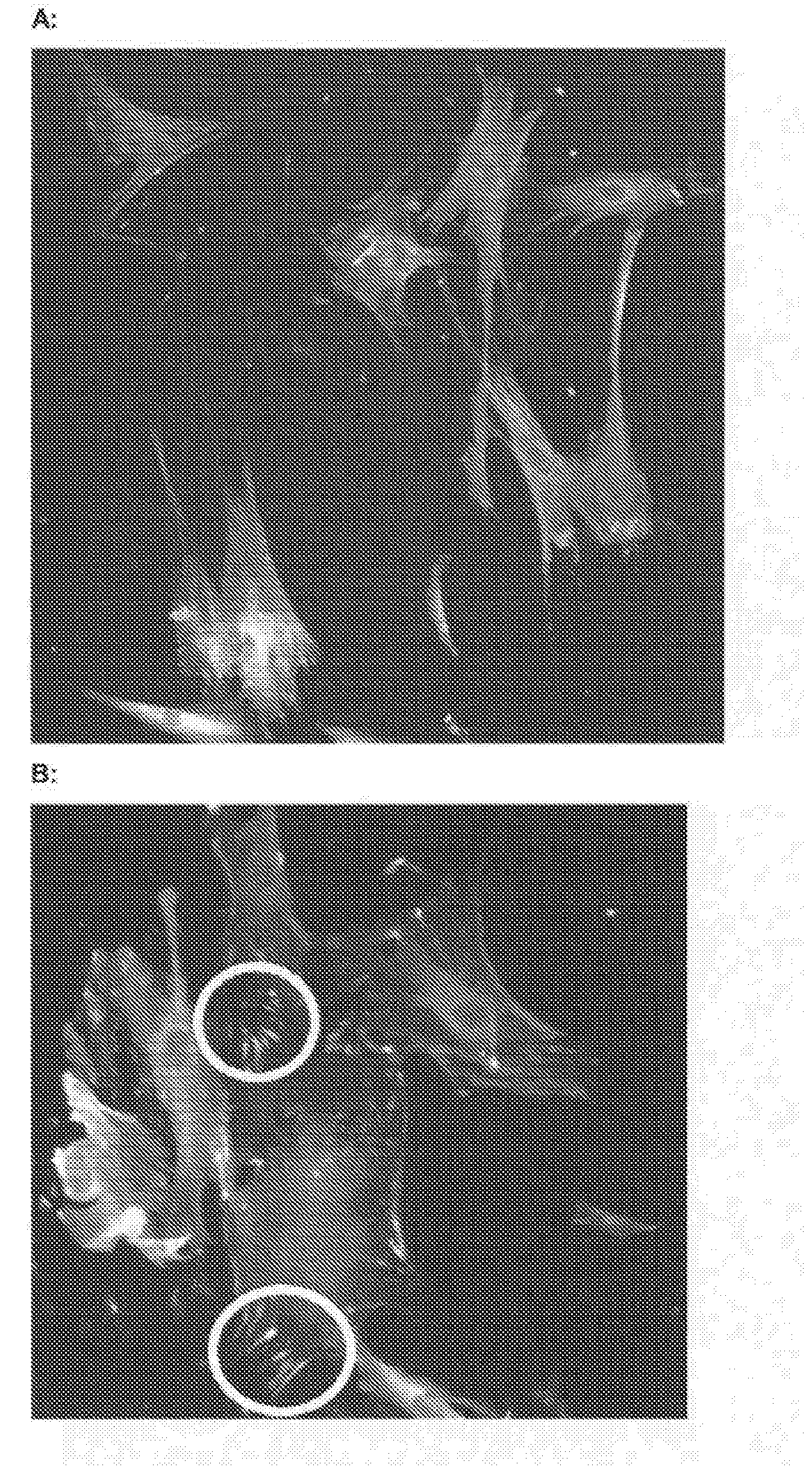
BDF's on ADM BM C After 6 Hours

[0521]As Seen in FIG. 14, after 6 hours BDF's on ADM BM C according to the invention have attached and are beginning to spread on the surface (white circle indicates a BDF which is displaying typical fibroblast spread morphology)

[0522]FIG. 15 shows Scanning Electron Microscope (SEM) images of BDF's on an ADM BM surfaces according to the invention after 24hrs (A) and 48 hours (B, C and D). It is clear to see the spread morphology of the cells on the ADM surface (white circles indicate BDF's which are displaying typical fibroblast spread morphology).

Discussion

[0523]ADM BM surface has been comprehensively characterized using a variety of imaging and measuring instruments. Commercially available smooth (Mentor Smooth) and textured (Mentor Textured) implants have also been characterized using the same methods, and have been compared to ADM BM. Extensive quantitative and qualitative data on all surfaces has been gathered, and a number of significant and stri...


PUM

PropertyMeasurementUnit
Lengthaaaaaaaaaa
Lengthaaaaaaaaaa
Lengthaaaaaaaaaa

Abstract

The invention provides new devices for implantation in a patient having irregular textured surfaces, which devices show significantly improved cellular response compared to conventional smooth and textured implants, indicating that significantly improved biocompatibility would be achieved in vivo. Methods for making such new devices and surface textures are also disclosed.

Description

TECHNICAL FIELD[0001]This invention relates to biocompatible implant materials having textured surface topographies for reducing capsular contracture and an undesirable cellular response upon implantation into the body, with particular application to prosthetic implants, such as silicone breast implants. Methods for preparing such surfaces are also disclosed.BACKGROUND[0002]Fibrous capsule formation around soft tissue body implants remains a persistent problem for many patients following prosthesis implantation. Silicone shell breast implants are particularly troublesome with potential development of capsular contracture, which is considered to be one of the primary reasons for device failure.Capsular Contracture[0003]The pathoetiology of capsular contracture formation around silicone mammary implants is both complex and enigmatic, however; it is thought to be an over-exaggeration of the normal foreign body reaction. There are a number of known risk factors for its development such ...

Claims


Application Information

Patent Timeline
IPC IPC(8): A61F2/00G03F7/00H01J37/305A61F2/12
CPCA61F2/0077A61F2/12G03F7/0037H01J37/3056A61F2002/0081A61F2002/0086B29L2031/7532H01J2237/3174B29C67/0059B33Y10/00B33Y80/00B29K2083/00A61F2240/004B29C64/112
Inventor BAYAT, ARDESHIRHILL, ERNIEKYLE, DANIELOIKONOMOU, ANTONIOS
Owner ESTAB LABS
Why Eureka
Try Eureka