Locking mechanism and electronic device having the same

Active Publication Date: 2012-11-15
WISTRON CORP
View PDF11 Cites 0 Cited by
  • Summary
  • Abstract
  • Description
  • Claims
  • Application Information

AI Technical Summary

Benefits of technology

[0010]a locking member snapped onto the cover so as to prevent removal of the object from the mounting space through the mounting port in a direction opposite to the mounting direction, in such a manner that a portion of the locking member is disposed in proximity to the mounting port and abuts against one of the sides of the object facing the mounting port.
[0015]a locking mechanism including a housing and a locking member, the housing including a base wall and a cover extending from the base wall to form a mounting space therebetween, and a mounting port in spatial communication with the mounting space and permitting the object to be moved into the mounting space therethrough in a mounting direction, the locking member being snapped onto the cover so as to prevent removal of the object from the mounting space through the mounting port in a direction opposite to the mounting direction, in such a manner that a portion of the locking member is disposed in proximity to the mounting port and abuts against one of the sides of the object facing the mounting port.

Problems solved by technology

As such, the magnetic-locking construction cannot lock effectively the magnet.

Method used


Image

  • Locking mechanism and electronic device having the same
  • Locking mechanism and electronic device having the same
  • Locking mechanism and electronic device having the same

Examples


Embodiment Construction

[0027]Before the present invention is described in greater detail in connection with the embodiments, it should be noted that similar elements and structures are designated by like reference numerals throughout the entire disclosure.

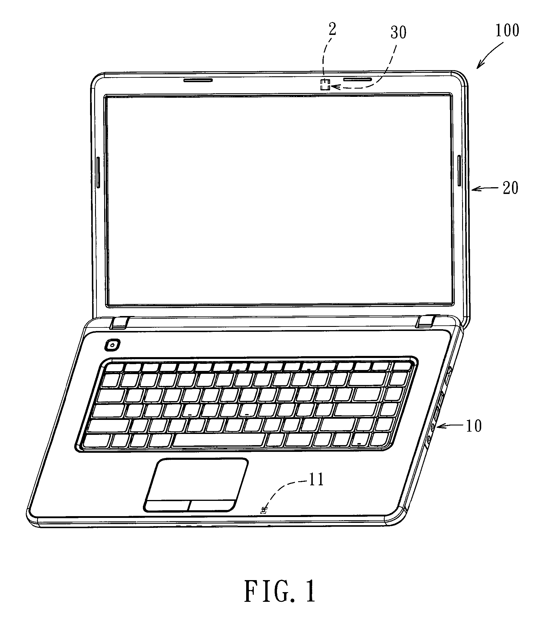
[0028]Referring to FIG. 1, the first embodiment of an electronic device 100 according to this invention includes a first body 10 and a second body 20 having a side connected pivotally to a side of the first body 10. In this embodiment, the electronic device 100 is exemplified using a notebook computer. Alternatively, the electronic device 100 may be a mobile phone or a personal digital assistant.

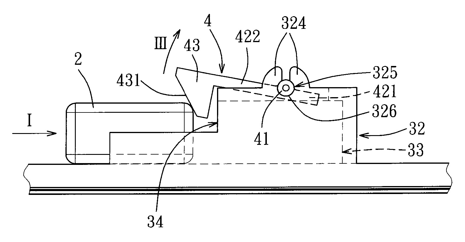
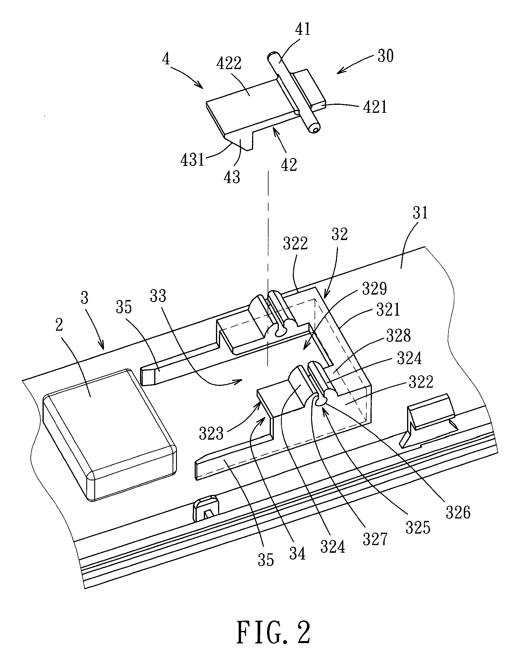
[0029]With additional reference to FIG. 2, the first body 10 is a host provided with electronic elements including a motherboard, a hard disk drive, an optical disk drive, etc. The first body 10 includes a magnetically conducting element 11, such as a metallic sheet or a magnet. The second body 20 is a display for covering the first body 10, and includes an objec...


PUM


Abstract

A locking mechanism is adapted for locking an object, and includes a housing and a locking member. The housing includes a base wall and a cover extending from the base wall to form amounting space therebetween, and amounting port in spatial communication with the mounting space and adapted for permitting the object to be moved into the mounting space therethrough in amounting direction. The locking member is snapped onto the cover so as to prevent removal of the object from the mounting space through the mounting port in a direction opposite to the mounting direction, in such a manner that a portion of the locking member is disposed in proximity to the mounting port and abuts against one of the sides of the object facing the mounting port.

Description

CROSS-REFERENCE TO RELATED APPLICATION[0001]This application claims priority of Taiwanese Application No. 100116134, filed on May 9, 2011, the disclosure of which is incorporated herein by reference.BACKGROUND OF THE INVENTION[0002]1. Field of the Invention[0003]This invention relates to a locking mechanism, and more particularly to a locking mechanism for locking an object on an electronic device.[0004]2. Description of the Related Art[0005]Taiwanese Patent No. M348452 discloses a magnet-locking construction and a notebook computer having the same. The magnet-locking construction includes a bottom plate and a top wall. A first sidewall, a second sidewall, a third sidewall are connected between the'top and bottom plate. An inlet is formed between the bottom plate and the top wall to allow a magnet to be placed into a space between the second and third sidewalls through the inlet. The distance between the second and third sidewalls is smaller than the width of the magnet, and the thi...

Claims


Application Information

Patent Timeline
IPC IPC(8): H05K7/00F16B2/10F16M13/00
CPCG06F1/1679G06F1/1616Y10T292/0911Y10T292/11
Inventor LIANG, CHEN-YICHUANG, CHENG-HSIANGCHEN, CHUN-CHIENBAI, SHUN-DEKAO, SAN-PAO
Owner WISTRON CORP
Why Eureka
Try Eureka