Adjustable slope ceiling recessed light fixture

a recessed light fixture and slope technology, applied in the direction of fixed installation, lighting and heating equipment, lighting support devices, etc., can solve the problems of reducing the life of the fixture, affecting the performance of the fixture, and affecting the quality of the fixtur

Active Publication Date: 2012-11-15
ABL IP HLDG
View PDF5 Cites 81 Cited by
  • Summary
  • Abstract
  • Description
  • Claims
  • Application Information

AI Technical Summary

Benefits of technology

[0005]Provided herein is a recessed fixture for being mounted within a sloped, or inclined, ceiling, and an associated adjustable heat sink assembly therefore. The heat sink assembly has two parts, a sliding plate adapted for mounting a fixture, such as, for example, an LED lig...

Problems solved by technology

LEDs are particularly sensitive to degradation due to excessive heat, and over time, their luminance...

Method used


Image

  • Adjustable slope ceiling recessed light fixture
  • Adjustable slope ceiling recessed light fixture
  • Adjustable slope ceiling recessed light fixture

Examples


Embodiment Construction

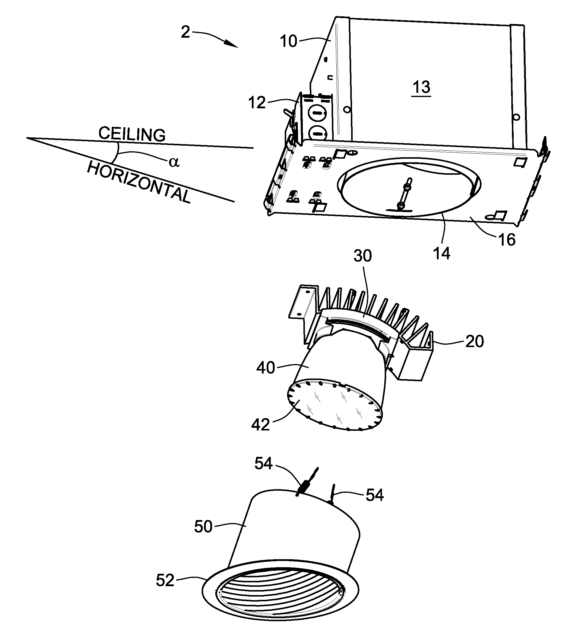
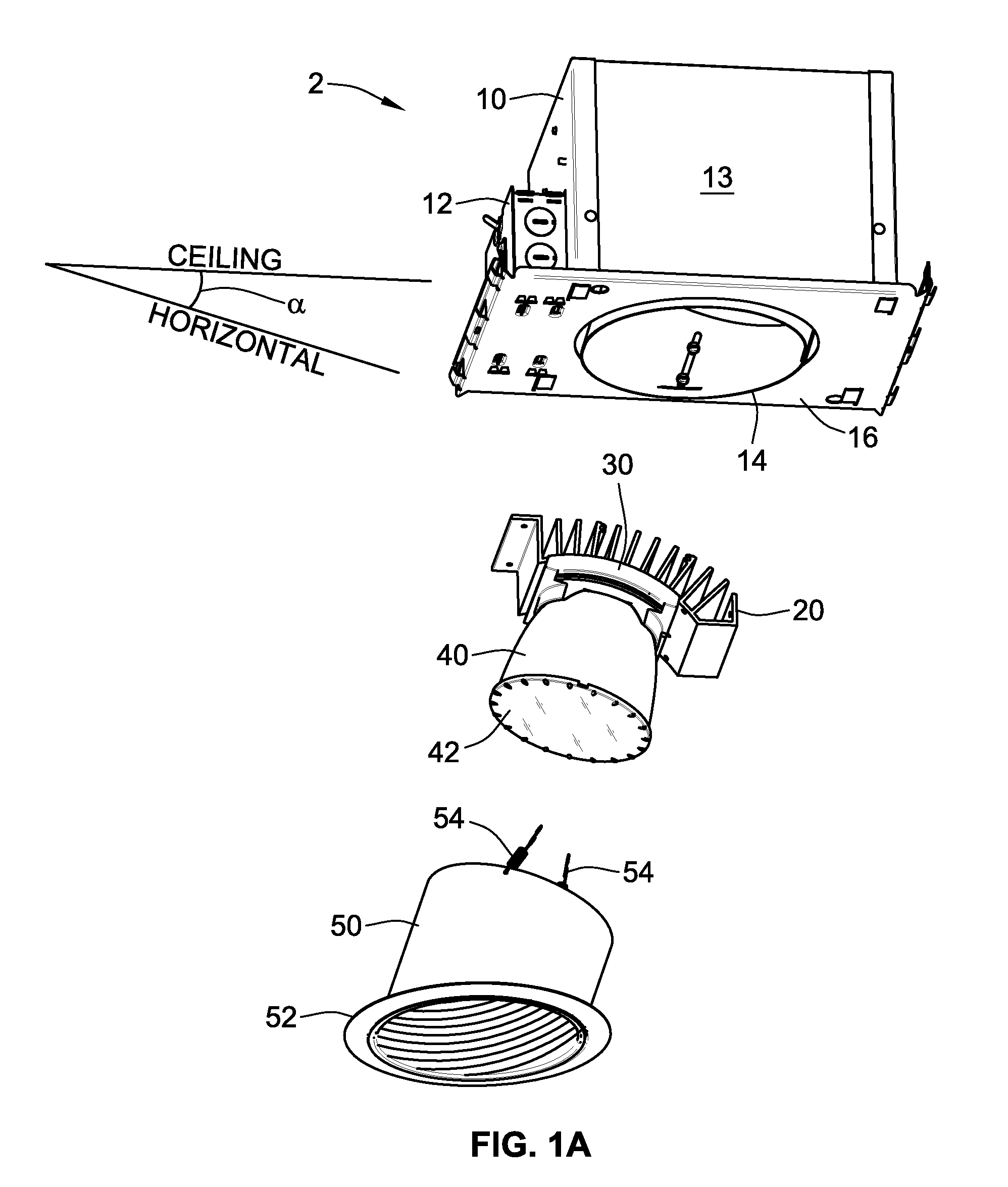
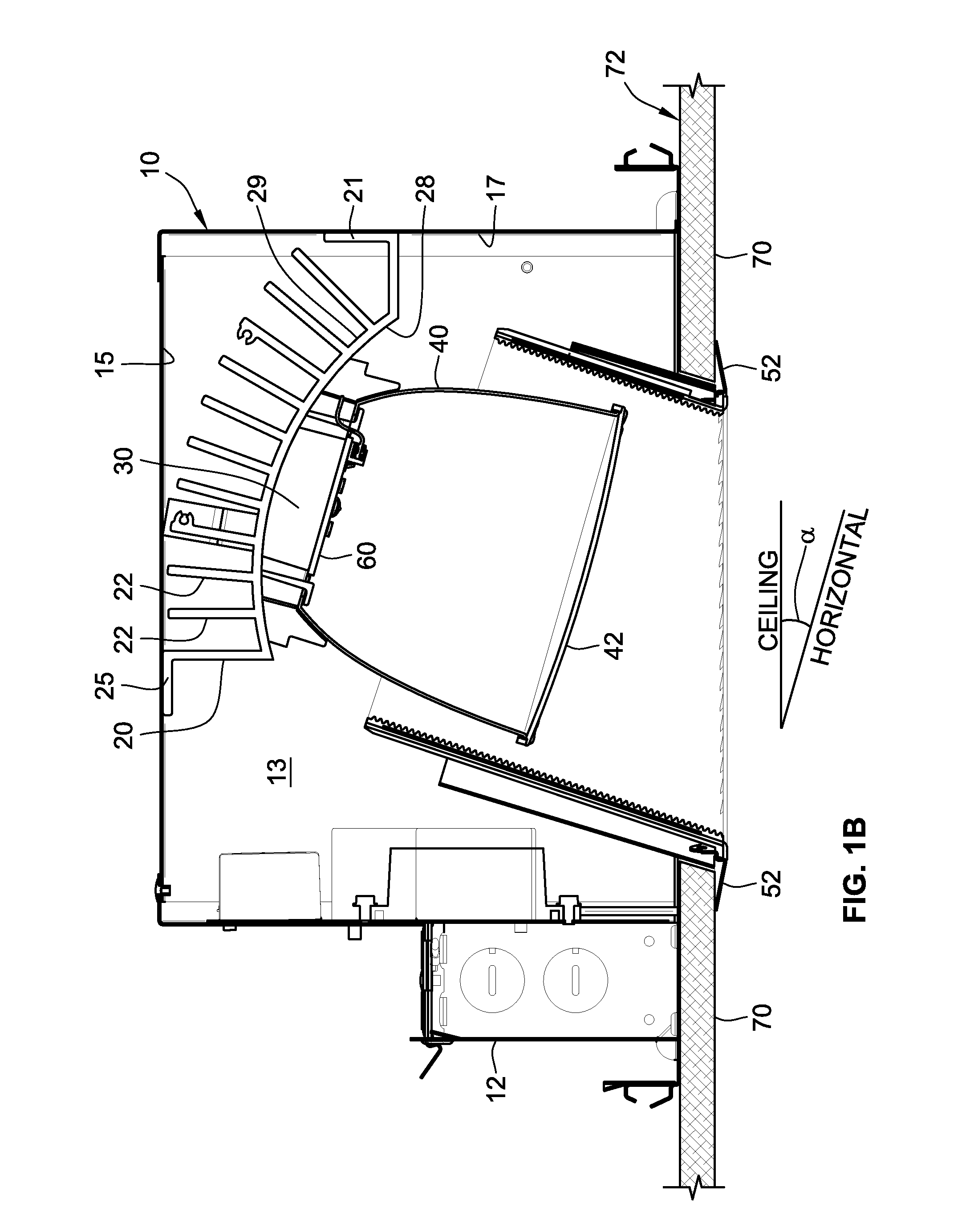
[0019]FIG. 1A is an exploded view of a recessed lighting fixture according to an implementation of the present disclosure. FIG. 1B is an assembled view of a profile cross-section of the recessed lighting fixture shown in FIG. 1A. The recessed lighting fixture shown in FIGS. 1A and 1B includes a rough-in box 2, a fixed heat sink 20, a sliding plate 30, an LED panel 60 (FIG. 1B), a reflector 40, a lens 42, a baffle 50, and a trim ring 52.

[0020]The rough-in box 2 includes an enclosure 10, a junction box 12, and bar hangers (not shown). The rough-in box 2 is adapted to be mounted within a recessed cavity of a finished construction, such as a recessed cavity of a finished sloped ceiling. The enclosure can be mounted within a recessed cavity of a suspended ceiling, or of a ceiling constructed with joists, such as wood joists. Using bar hangers and / or aspects of the rough-in box 2 securely coupled or integrally formed with the enclosure 10, the rough-in box 2 can be mounted in a recessed c...


PUM


Abstract

An adjustable assembly for conveying heat away from a fixture. The adjustable assembly includes a sliding plate having a first side for mounting the fixture thereon and a curved surface opposite the first side. The adjustable assembly also includes a fixed heat sink having a mating surface adapted to allow the curved surface of the sliding plate to slide from a first position to a second position while maintaining a substantially flush contact between the curved surface of the sliding plate and the mating surface of the fixed heat sink. At least one fastener is also provided for securing the sliding plate to the fixed heat sink alternately in the first position or the second position.

Description

CROSS REFERENCE TO RELATED APPLICATIONS[0001]This application claims priority to U.S. Provisional Application No. 61 / 484,208, filed May 9, 2011, the contents of which is incorporated entirely herein by reference.FIELD OF THE INVENTION[0002]The present disclosure relates generally to recessed lighting fixtures, and, more particularly, to an adjustable recessed light fixture for mounting in a sloped or inclined ceiling and to a heat sink therefore.BACKGROUND[0003]Light emitting diodes (“LEDs”) offer some advantageous over other types of lighting fixtures, such as incandescent and fluorescent lighting fixtures. LED lighting fixtures are generally more energy efficient, have longer operating lives, and contain less harmful products simplifying waste management and recycling requirements. Unlike recessed fixtures in which the light source is an incandescent, fluorescent, or halogen bulb, for example, in recessed fixtures having LEDs as the light source, the heat generated by the LEDs rad...

Claims


Application Information

Patent Timeline
IPC IPC(8): F21V7/00F21V29/00F21V15/01F21S8/08F21S4/00
CPCF21V29/004F21S8/026F21V7/00F21V21/14F21V17/002F21V17/02F21V29/89F21V17/162F21Y2101/02F21Y2105/001F21V29/507F21V29/713F21V29/777F21V17/14F21Y2105/10F21Y2115/10
Inventor MACWAN, MAHENDRA JOSEPHSTAUNER, JOSEPHFONG, FRANKLIN
Owner ABL IP HLDG
Why Eureka
Try Eureka