Apparatus and method for lorentz-active sheath display and control of surgical tools

a technology of active sheaths and apparatus, applied in the field of lorentz-active sheath display and control of surgical tools, can solve the problems of reliable fix, and inability to provide a consistent fix in the prior art, and achieve the effect of accurate assessment of the true position of the sheath within the patien

Inactive Publication Date: 2012-11-15
NEURO KINESIS CORP
View PDF29 Cites 21 Cited by
  • Summary
  • Abstract
  • Description
  • Claims
  • Application Information

AI Technical Summary

Benefits of technology

[0010]One embodiment includes a system that can continually determine the position and location of the distal tip of a medical sheath and track its movements in six degrees of freedom as it is manipulated through a patient while compensating for the movement of the patient or organ it is working in without the use of fluoroscopy or other medical imaging devices that use an ionizing field source.
[0014]In one embodiment, the position and orientation error values of the LAS are used to subtract the motion of the LAS from the motion of the LAS-hosted medical tool. This in effect along with the previous three embodiments forms a motion compensation filter and provides a stable fiducial reference for tool position control systems and thus provides the operating physician with an accurate assessment of the sheath's true position within the patient.

Problems solved by technology

While the prior art has been successful in treating many patients, the techniques of the prior art are not without their drawbacks and difficulties.
The prior art does not provide a consistent, and reliable fix on the location of the sheath as well as maintaining a known orientation of the distal tip of the sheath.
The prior art uses fiducial markers such as the ones presented above which can only be seen when using an ionizing field source such as an x-ray or CT scan and are useless when employed in a radar based navigation system.
The prior art has so far failed to employ the sheath itself for motion compensation.

Method used


Image

  • Apparatus and method for lorentz-active sheath display and control of surgical tools
  • Apparatus and method for lorentz-active sheath display and control of surgical tools
  • Apparatus and method for lorentz-active sheath display and control of surgical tools

Examples


Embodiment Construction

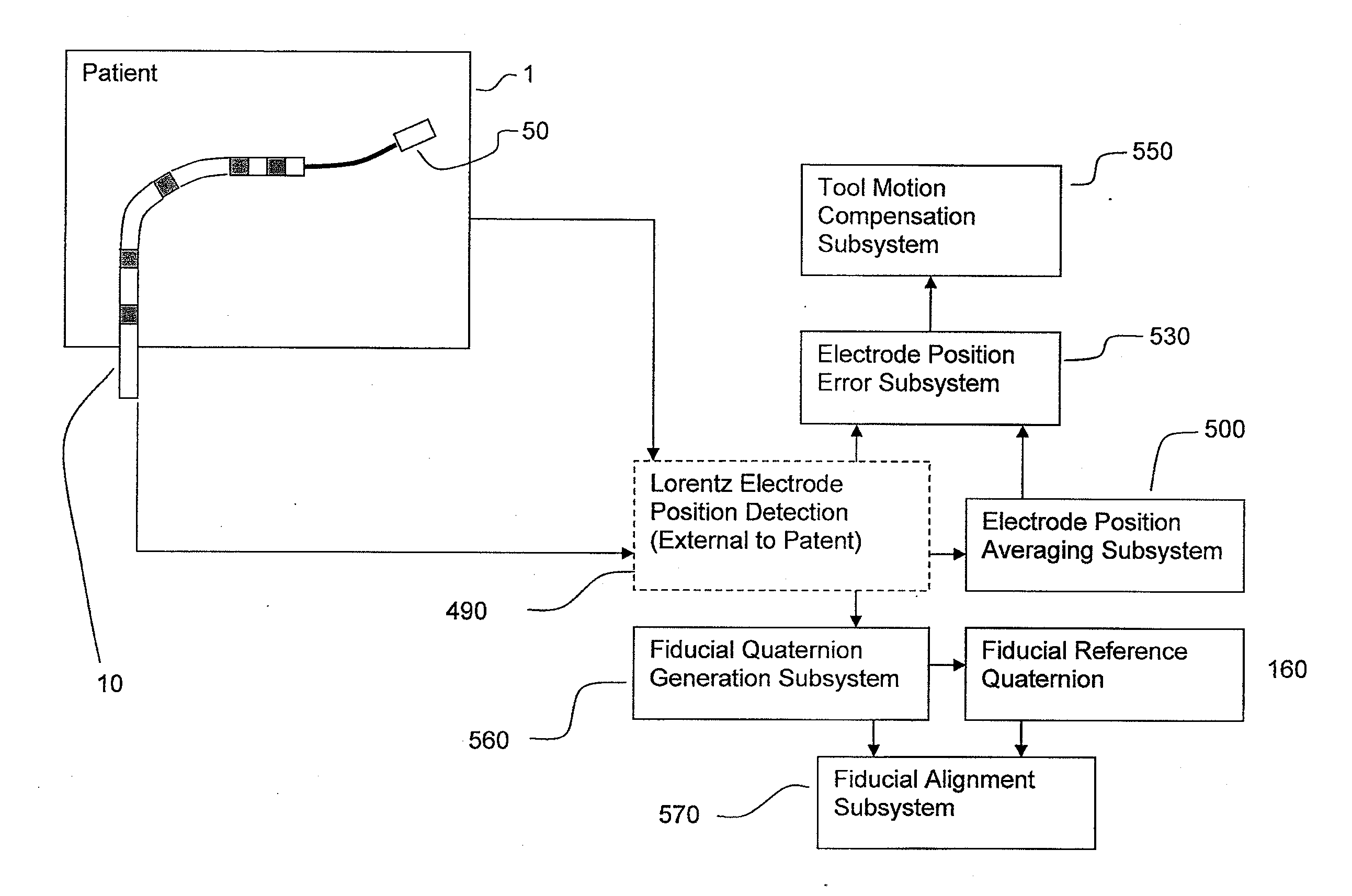
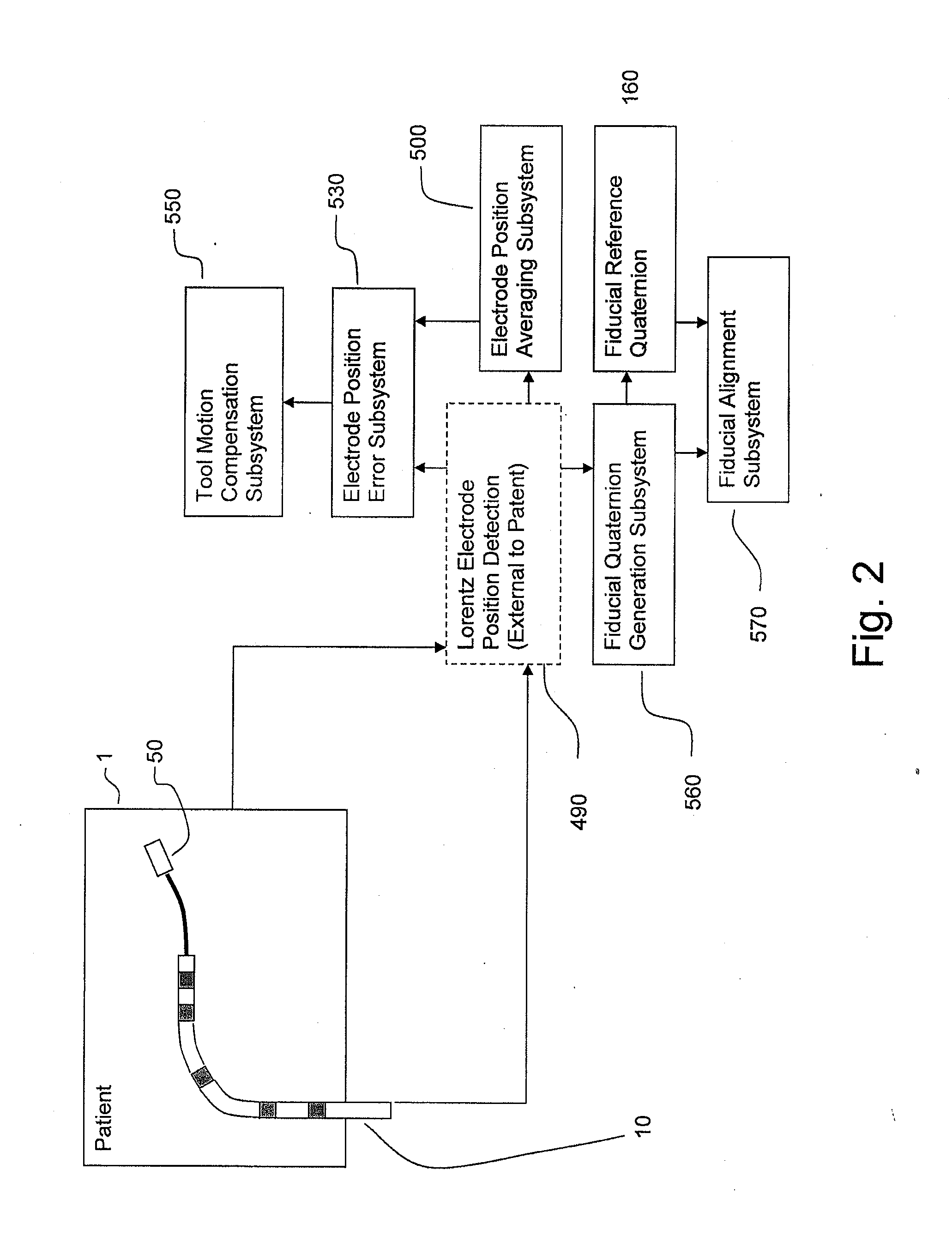
[0025]In general, the Lorentz-Active Sheath (LAS) serves as a conduit for other medical devices such as catheters, balloons, biopsy needles, etc. The sheath is inserted through a vein or other body orifice and is guided into the area of the patient where the operation is to be performed. The position and orientation of the LAS is tracked via a conventional position detection system which senses electrical signals that are emitted from several electrodes coupled to the LAS. The signals received from the LAS are used to calculate an accurate and reliable assessment of the actual position of the LAS within the patient. The electrode signals also serve to create a reference frame which is then used to act as a motion compensation filter and fiducial alignment system for the movement of the LAS-hosted medical tool.

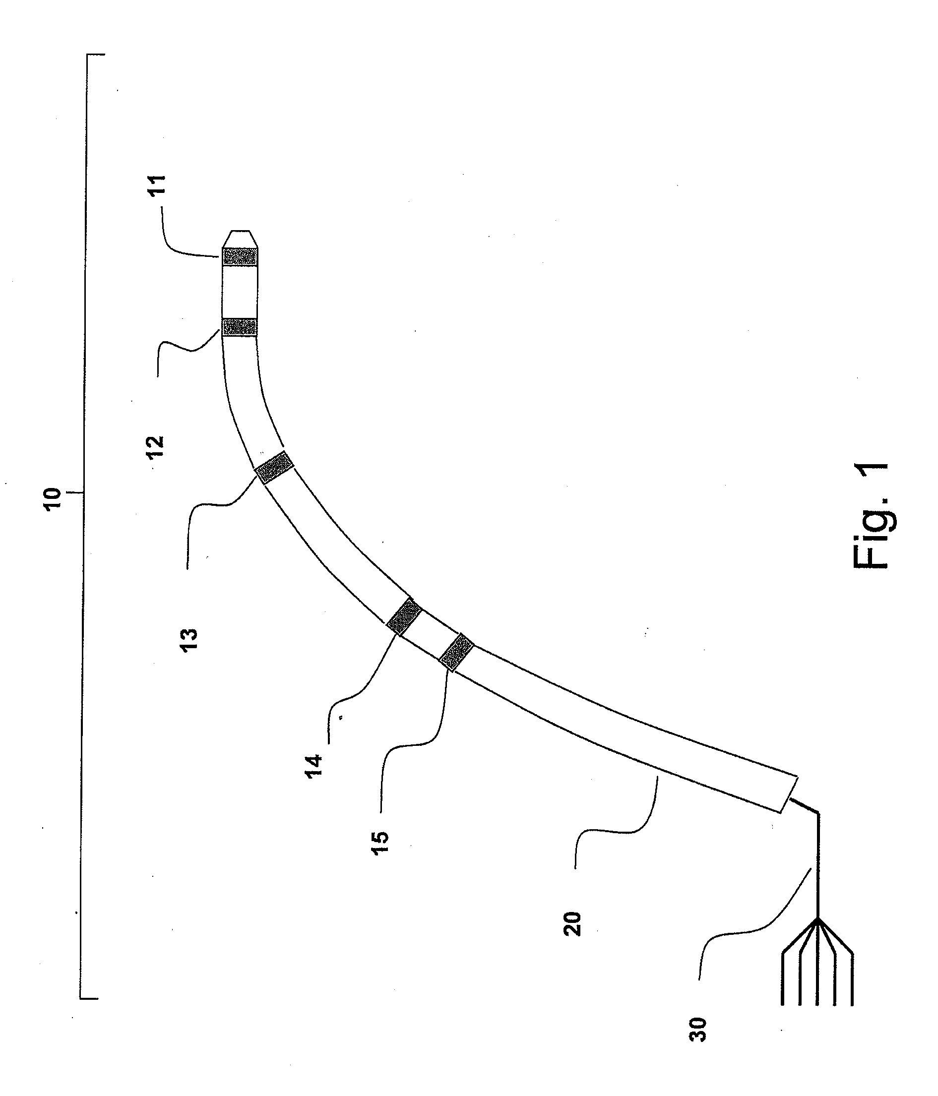
[0026]FIG. 1 is an isometric diagram of the LAS assembly 10. Detection system-sensitive electrodes 11-15 are integrated into the LAS shaft 20. The electrodes 11-15 are used to ...


PUM


Abstract

The Lorentz-Active Sheath (LAS) serves as a conduit for other medical devices such as catheters, balloons, biopsy needles, etc. The sheath is inserted through a vein or other body orifice and is guided into the area of the patient where the operation is to be performed. The position and orientation of the LAS is tracked via an industry standard position detection system which senses electrical signals that are emitted from several electrodes coupled to the LAS. The signals received from the LAS are used to calculate an accurate and reliable assessment of the actual position of the LAS within the patient. The electrode signals also serve to create a reference frame which is then used to act as a motion compensation filter and fiducial alignment system for the movement of the LAS-hosted medical tool.

Description

CROSS-REFERENCE TO RELATED APPLICATIONS[0001]This application is a continuation of U.S. patent application Ser. No. 12 / 099,079, filed Apr. 7, 2008, the entirety of which is incorporated herein by reference and is to be considered part of this specification.BACKGROUND OF THE INVENTION[0002]1. Field of the Invention[0003]The invention relates to the field of determining the location, orientation, and movement of an invasive medical device within a patient while compensating for undesired tool and patient motion.[0004]2. Description of the Related Art[0005]Medical sheaths have long been used to introduce a variety of medical tools into a patient during an operation. Typically, the sheath is inserted into the patient via a vein or other orifice and is manipulated until it has reached its target location such as a ventricle of the heart. Invasive medical tools such as catheters, balloons, and biopsy needles are then deployed through the sheath in order to work on the patient.[0006]While ...

Claims


Application Information

Patent Timeline
Patent Type & Authority Applications(United States)
IPC IPC(8): A61B1/32A61B6/00
CPCA61B5/06A61B1/018A61B5/061A61B5/062A61B5/064A61B5/065
Inventor SHACHAR, YEHOSHUAMARX, BRUCEFARKAS, LESLIEJOHNSON, DAVIDFARKAS, LASZLO
Owner NEURO KINESIS CORP
Why Eureka
Try Eureka