Temporary anchor for a hearing prosthesis

Inactive Publication Date: 2012-11-22
KRISTO STEFAN +2
View PDF43 Cites 50 Cited by
  • Summary
  • Abstract
  • Description
  • Claims
  • Application Information

AI Technical Summary

Benefits of technology

[0009]In accordance with another aspect of the present invention, a method for using a temporary anchor having a first surface adapted to adhere to the adhesive element, and a fixture adapted to attach to a coupler of t

Problems solved by technology

Conductive hearing loss occurs when the normal mechanical pathways that provide sound to hair

Method used


Image

  • Temporary anchor for a hearing prosthesis
  • Temporary anchor for a hearing prosthesis
  • Temporary anchor for a hearing prosthesis

Examples


Embodiment Construction

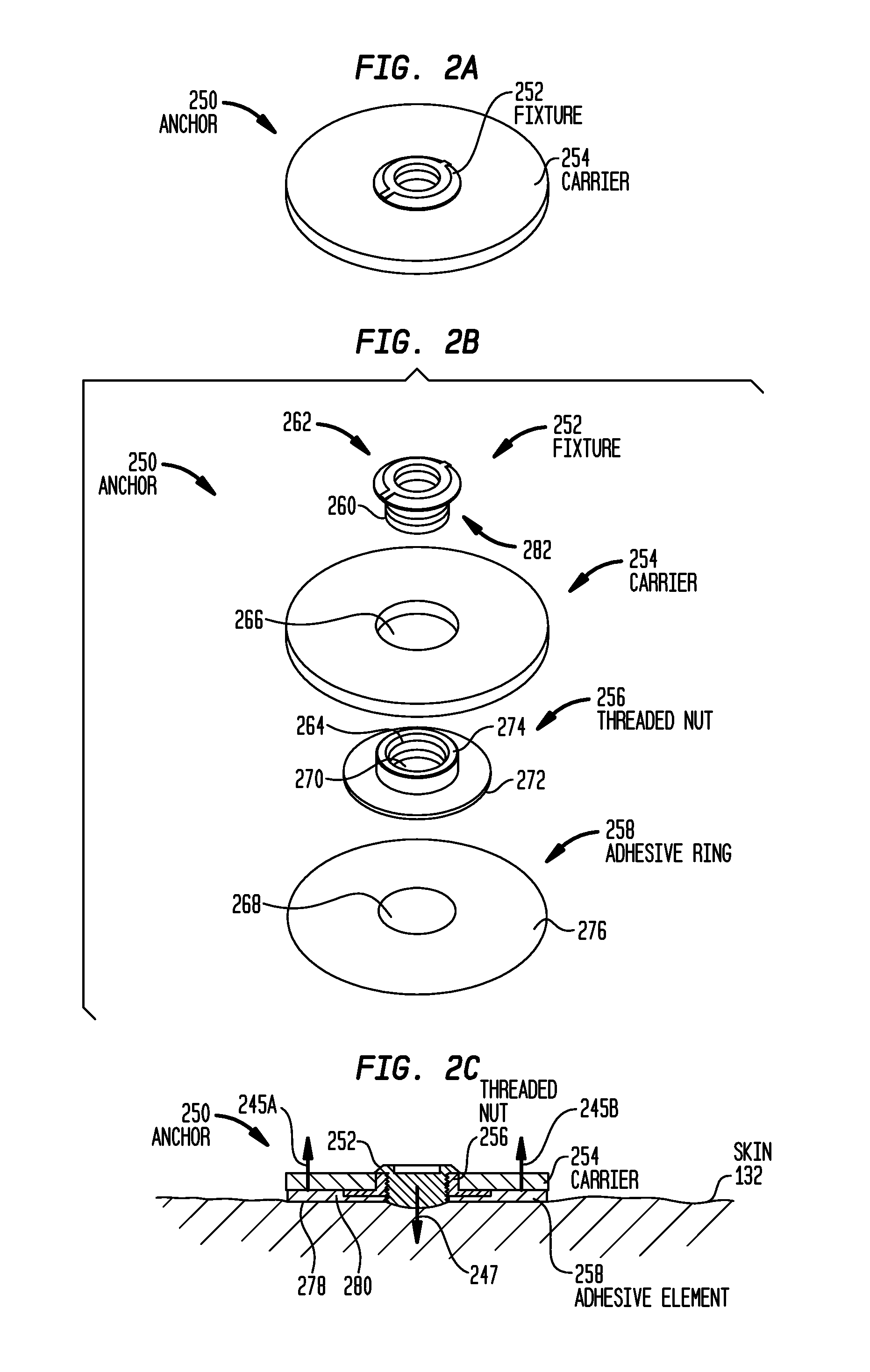
[0028]Aspects of the present invention are generally directed to a temporary anchor for a hearing prosthesis. The anchor is adapted to be affixed to a recipient's skin via an adhesive element, and comprises a fixture configured to attach to a coupler of a hearing prosthesis.

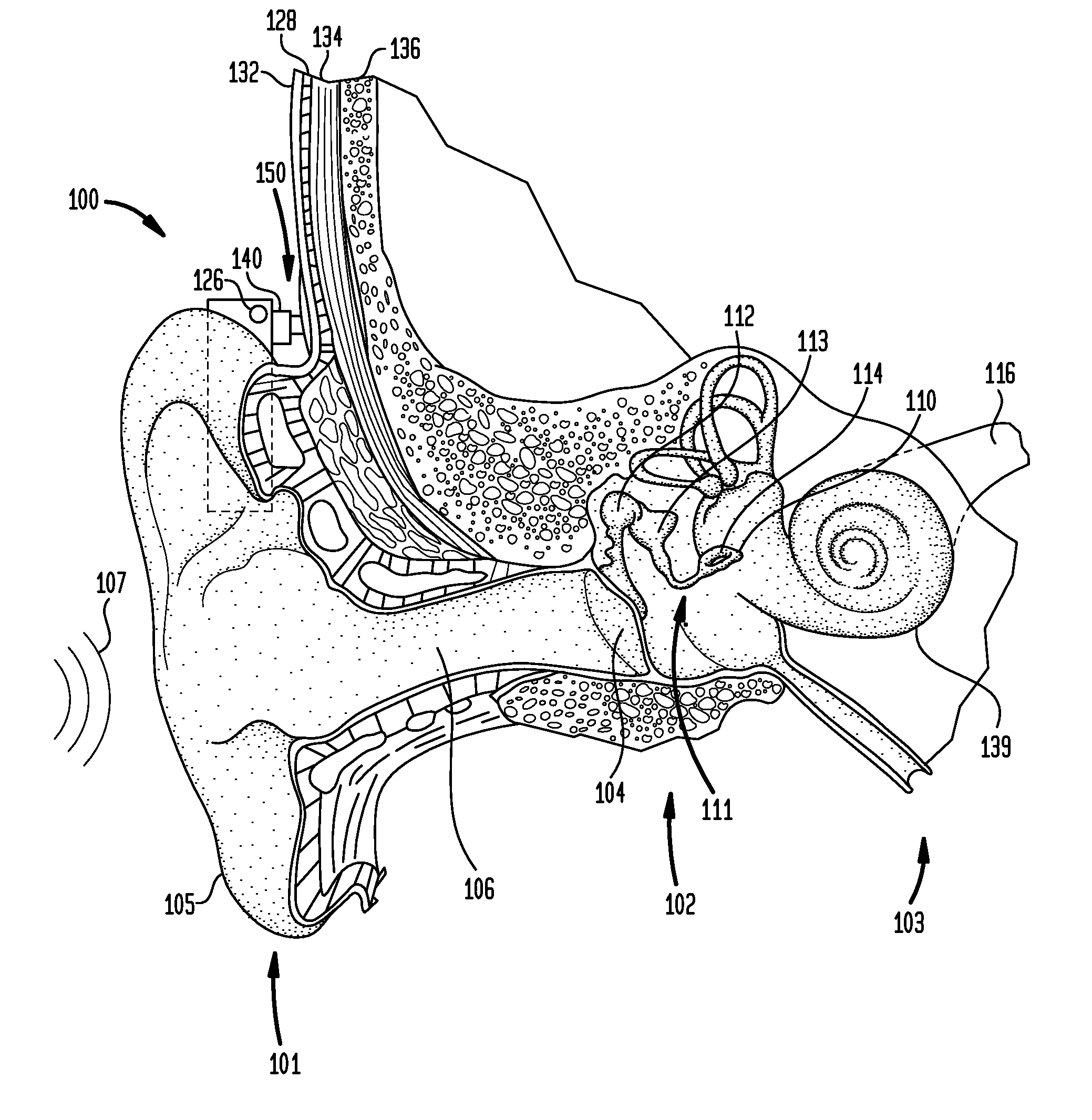
[0029]FIG. 1 is a perspective view of a conventional hearing prosthesis 100 having a coupling apparatus 140 attached to a temporary anchor 150, in accordance with embodiments of the present invention. As shown, the recipient has an outer ear 101, a middle ear 102 and an inner ear 103. Elements of outer ear 101, middle ear 102 and inner ear 103 are described below, followed by a description of hearing prosthesis 100.

[0030]In a fully functional human hearing anatomy, outer ear 101 comprises an auricle 105 and an ear canal 106. A sound wave or acoustic pressure 107 is collected by auricle 105 and channeled into and through ear canal 106. Disposed across the distal end of ear canal 106 is a tympanic membrane 104 whic...


PUM


Abstract

A hearing system, comprising: an adhesive element adapted to temporarily adhere to the skin of a recipient; a hearing prosthesis having a coupler and an anchor having a first surface adapted to adhere to the adhesive element, and a fixture adapted to attach to the coupler of the hearing prosthesis.

Description

BACKGROUND[0001]1. Field of the Invention[0002]The present invention relates generally to hearing prostheses, and more particularly, to a temporary anchor for a hearing prosthesis.[0003]2. Related Art[0004]Hearing loss, which may be due to many different causes, is generally of two types: conductive and sensorineural. Sensorineural hearing loss is due to the absence or destruction of the hair cells in the cochlea that transduce sound signals into nerve impulses. Various hearing prostheses are commercially available to provide individuals suffering from sensorineural hearing loss with the ability to perceive sound. For example, cochlear implants use an electrode array implanted in the cochlea of a recipient to bypass the mechanisms of the ear. More specifically, an electrical stimulus is provided via the electrode array to the auditory nerve, thereby causing a hearing percept.[0005]Conductive hearing loss occurs when the normal mechanical pathways that provide sound to hair cells in ...

Claims


Application Information

Patent Timeline
IPC IPC(8): H04R25/00
CPCH04R25/606
Inventor KRISTO, STEFANJEPPESEN, HENRIKPRA ME, MARTIN
Owner KRISTO STEFAN
Why Eureka
Try Eureka