
Separated target apparatus for sputtering and sputtering method using the same

a target apparatus and sputtering technology, applied in vacuum evaporation coatings, electrolysis components, coatings, etc., can solve the problems of tft completely formed, difficult to manufacture deposition, and significant load

Active Publication Date: 2012-11-29
SAMSUNG DISPLAY CO LTD
View PDF5 Cites 3 Cited by
  • Summary
  • Abstract
  • Description
  • Claims
  • Application Information

AI Technical Summary

Benefits of technology

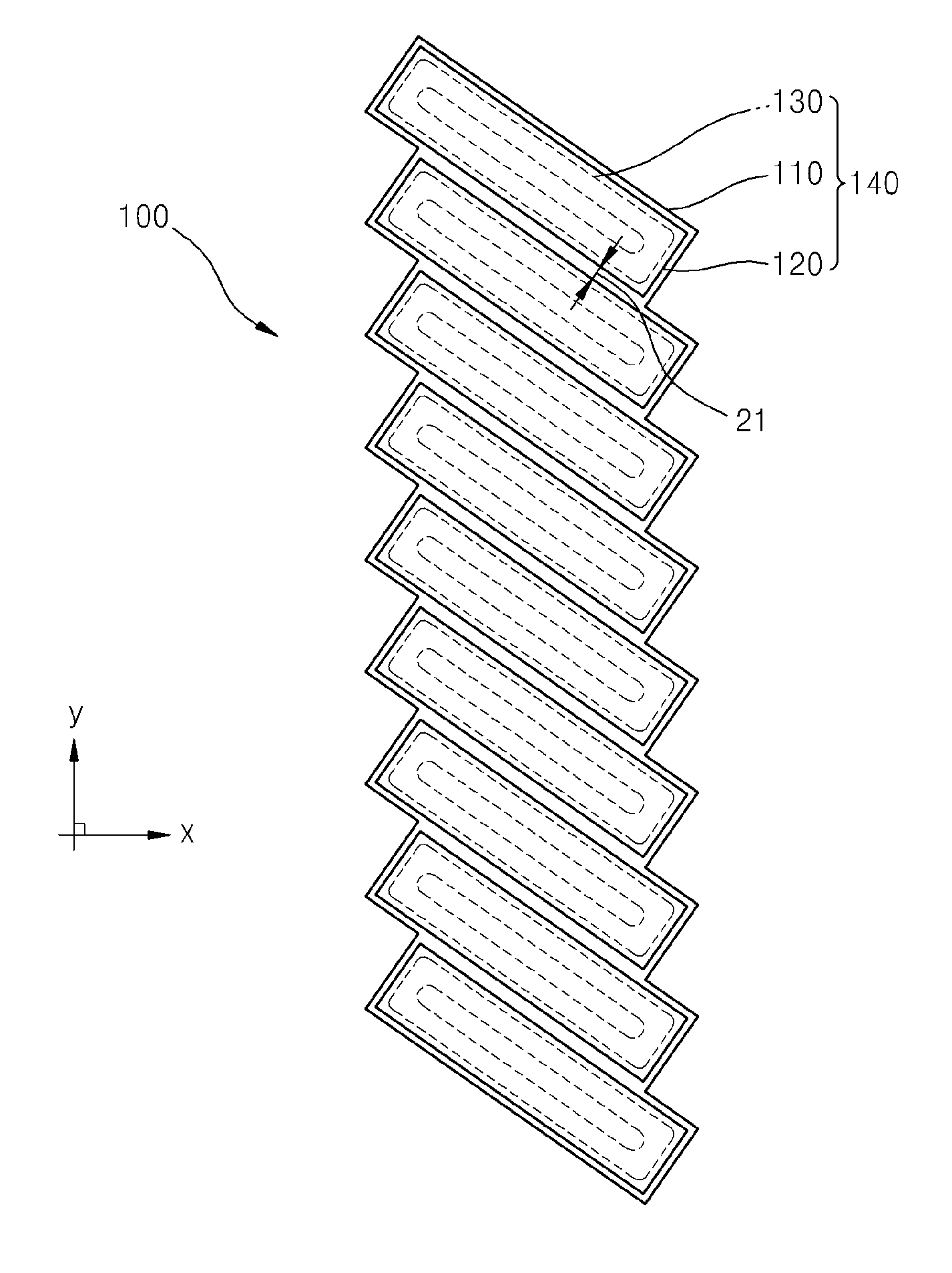
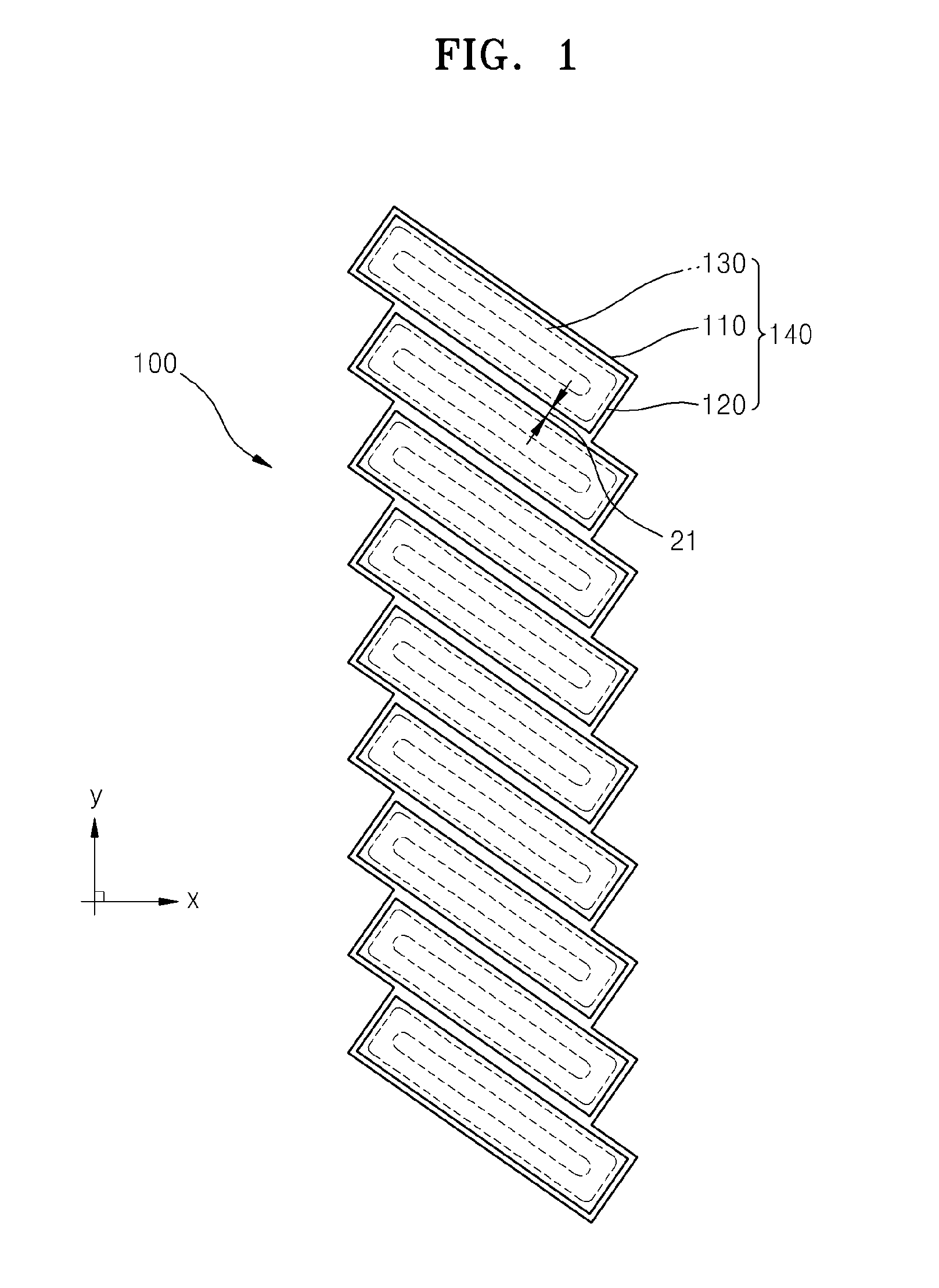
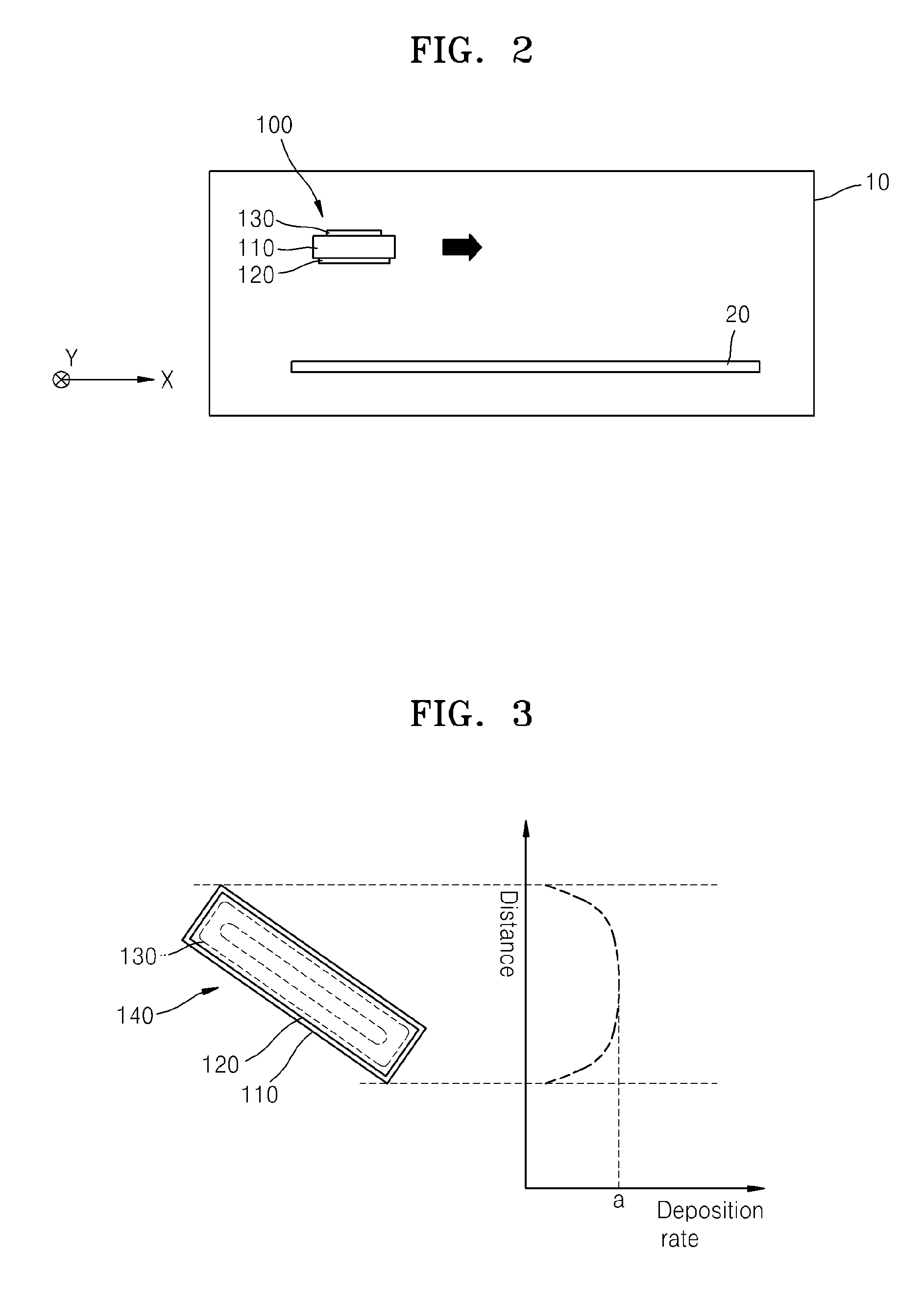
[0012]Exemplary embodiments of the present invention provide a separated target apparatus for sputtering which uses separated targets but restrains a deposition quality deviation in portions of a screen which causes a brightness deviation.

Problems solved by technology

However, as a size of a screen of the display apparatus increases, it becomes difficult to manufacture the deposition target so as to allow the deposition target to have the same size as the screen.
That is, the TFT is completely formed on the screen of the display apparatus, and in this regard, a significant load is caused in manufacturing and handling the deposition target so as to allow the deposition target to have almost the same size as the screen.
However, the oxide is fragile such that it is difficult to manufacture and to handle the oxide when the oxide is large.
Due to the aforementioned problems, brightness on a screen of a display apparatus that is a final product may not be uniform, and a level of a brightness deviation may increase in portion to the size of the screen.

Method used


Image

  • Separated target apparatus for sputtering and sputtering method using the same
  • Separated target apparatus for sputtering and sputtering method using the same
  • Separated target apparatus for sputtering and sputtering method using the same

Examples


Embodiment Construction

[0023]Hereinafter, the present invention will be described in detail by explaining exemplary embodiments of the invention with reference to the attached drawings, in which embodiments of the invention are shown. This invention may, however, be embodied in many different forms and should not be construed as limited to the embodiments set forth herein. Rather, these embodiments are provided so that this disclosure is thorough, and will fully convey the scope of the invention to those skilled in the art. In the drawings, the size and relative sizes of layers and regions may be exaggerated for clarity. Like reference numerals in the drawings denote like elements.

[0024]It will be understood that when an element or layer is referred to as being “on” or “connected to” another element or layer, it can be directly on or directly connected to the other element or layer, or intervening elements or layers may be present. In contrast, when an element or layer is referred to as being “directly on...


PUM

PropertyMeasurementUnit
angleaaaaaaaaaa
shapeaaaaaaaaaa
areaaaaaaaaaaa

Abstract

A separated target apparatus includes a base plate; and a plurality of source units including a plurality of separated targets that are adhered on one surface of the base plate and that form a regular array, and a plurality of magnets that are adhered on the other surface of the base plate and that make a pair with the plurality of separated targets. The plurality of source units are arrayed in parallel at an angle between a first direction that is a direction of the regular array and a second direction that is perpendicular to the first direction. Sputtering is performed by using the separated target apparatus having the aforementioned structure.

Description

CROSS REFERENCE TO RELATED PATENT APPLICATION[0001]This application claims priority from and the benefit of Korean Patent Application No. 10-2011-0048505, filed on May 23, 2011, which is hereby incorporated by reference for all purposes as if fully set forth herein.BACKGROUND OF THE INVENTION[0002]1. Field of the Invention[0003]Exemplary embodiments of the present invention relate to a separated target apparatus used as a deposition source in a sputtering operation, and a sputtering method using the separated target apparatus.[0004]2. Discussion of the Background[0005]In general, a thin film transistor (TFT) that is applied to a display apparatus is manufactured via a deposition process such as magnetron sputtering. That is, sputtering is performed on a deposition target so that a thin film having a desired pattern is formed on a substrate of the display apparatus which is a deposition target object.[0006]However, as a size of a screen of the display apparatus increases, it becomes ...

Claims


Application Information

Patent Timeline
Patent Type & Authority Applications(United States)
IPC IPC(8): C23C14/34C23C14/08
CPCC23C14/352C23C14/34H01J37/32568H01J37/3417
Inventor CHUNG, YUN-MOLEE, KI-YONGJEONG, MIN-JAE
Owner SAMSUNG DISPLAY CO LTD
Learn More