Method and system for fabricating a narrow line structure in a magnetic recording head

Inactive Publication Date: 2012-11-29
WESTERN DIGITAL TECH INC
View PDF8 Cites 161 Cited by
  • Summary
  • Abstract
  • Description
  • Claims
  • Application Information

AI Technical Summary

Benefits of technology

[0008]A method for fabricating a structure from layer(s) corresponding to the structure in magnetic recording head is described. The method includes providing a first hard mask layer on the layer(s) and a second hard mask layer on the first hard mask layer. A bottom antireflective coating (BARC) layer is provided on the second hard mask layer. A photoresist mask having a pattern is provided on the second hard mask layer. The pattern includes a line corresponding to the structure. The pattern is transferred to the BARC layer and

Problems solved by technology

The conventional method 10 may not be capable of fabricating a line at such small widths.
When such a thick resist line has such a na

Method used


Image

  • Method and system for fabricating a narrow line structure in a magnetic recording head
  • Method and system for fabricating a narrow line structure in a magnetic recording head
  • Method and system for fabricating a narrow line structure in a magnetic recording head

Examples


Embodiment Construction

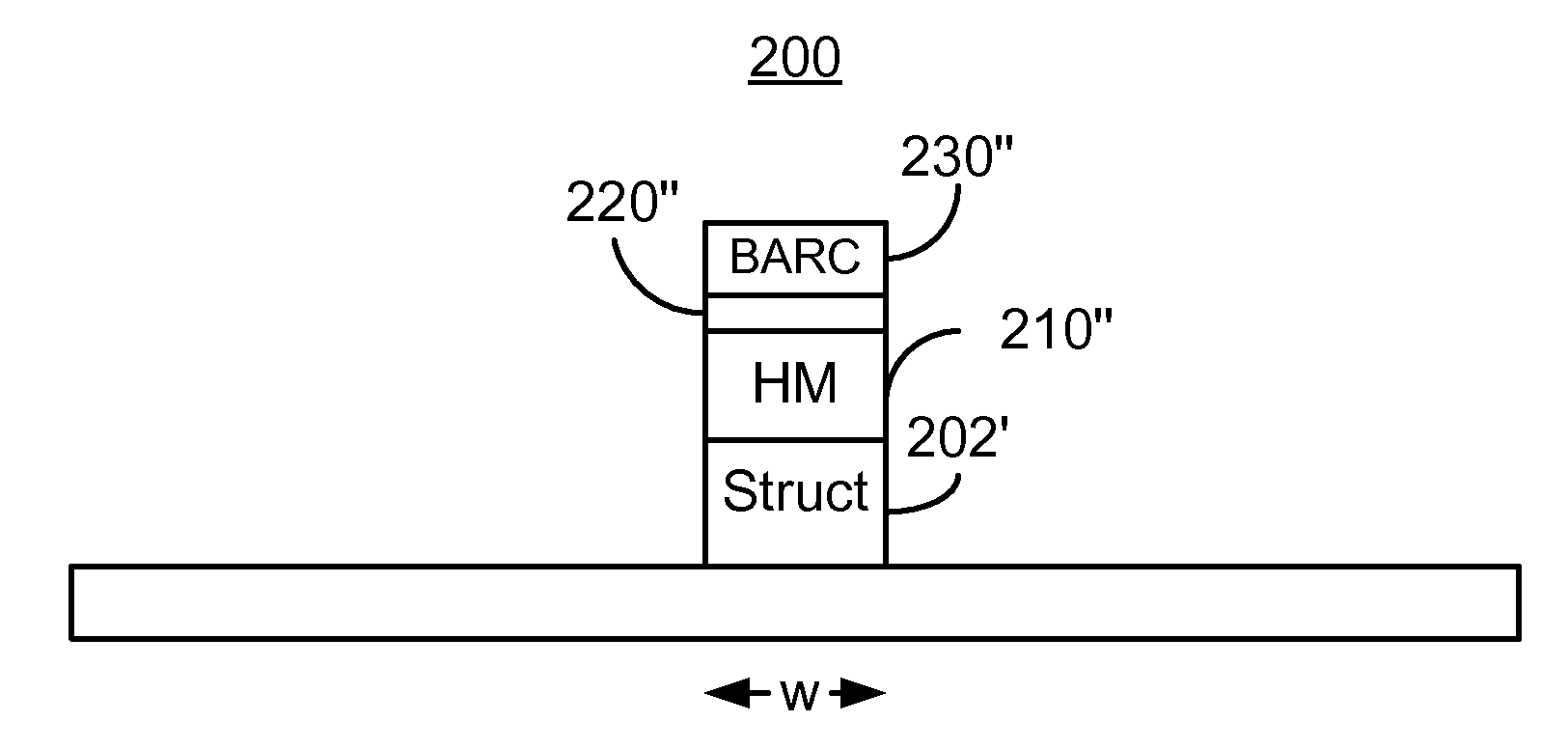
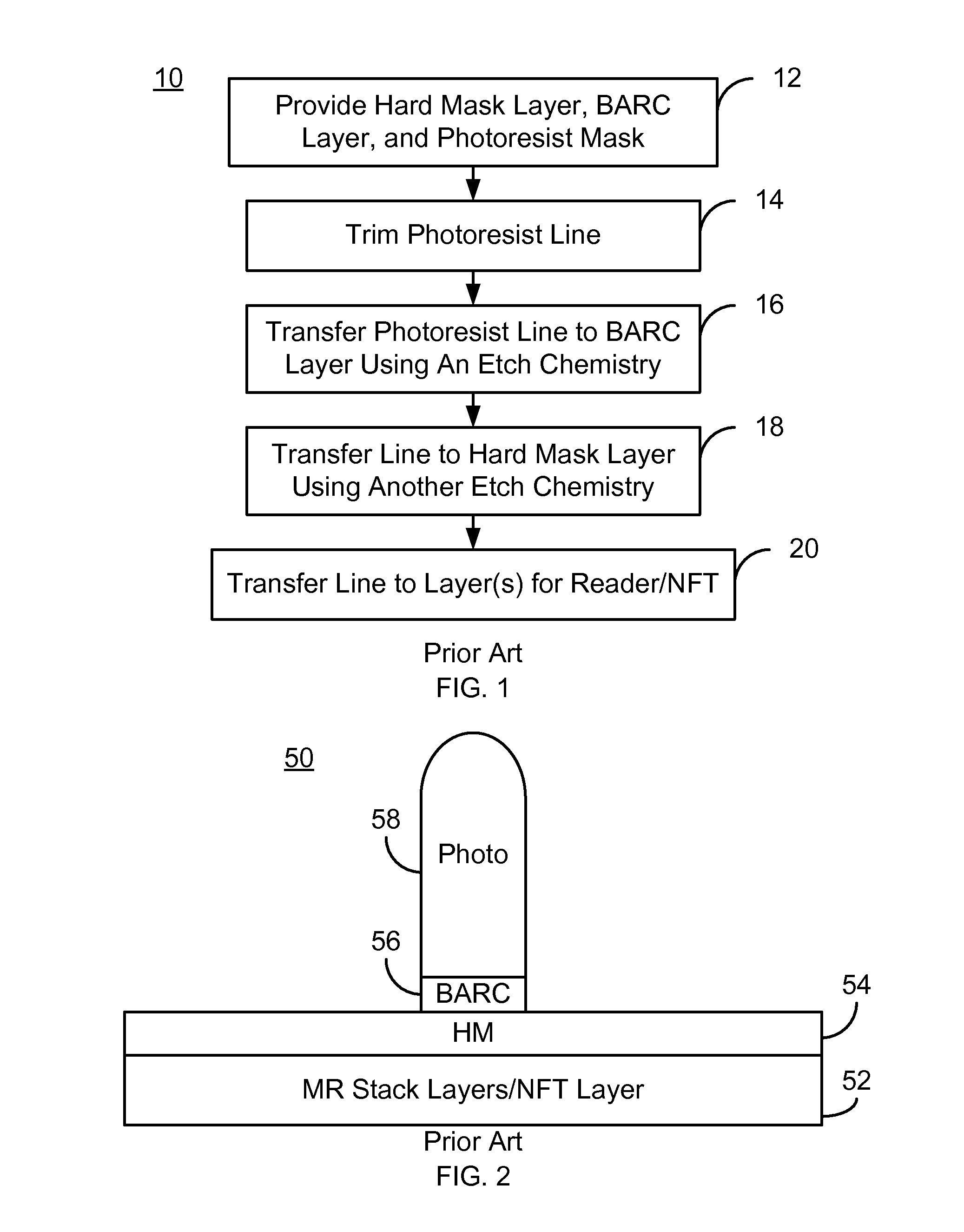
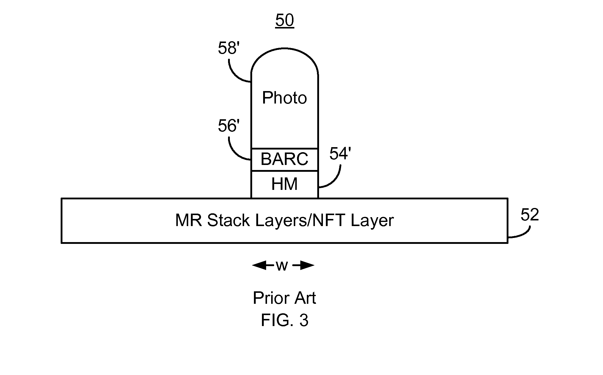
[0015]FIG. 4 is an exemplary embodiment of a method 100 for providing magnetic recording transducer. For simplicity, some steps may be omitted. The method 100 is also described in the context of providing a single recording transducer. However, the method 100 may be used to fabricate multiple transducers at substantially the same time. The method 100 is also described in the context of particular layers. A particular layer may include multiple materials and / or multiple sub-layers. The method 100 also may start after formation of other portions of the magnetic recording transducer. For example, the method 100 commences after deposition of layer(s) from which the structure is desired to be formed. For example, if a magnetoresistive sensor is to be formed, then the method 100 starts after the layers for a magnetoresistive stack have been deposited. The magnetoresistive layers may include a pinning layer, a pinned layer, a nonmagnetic spacer layer, and a free layer. In addition, seed an...


PUM


Abstract

A method for fabricating a structure in magnetic recording head is described. First and second hard mask layers are provided on the layer(s) for the structure. A BARC layer and photoresist mask having a pattern are provided on the second hard mask layer. The pattern includes a line corresponding to the structure. The pattern is transferred to the BARC layer and the second hard mask layer in a single etch using an etch chemistry. At least the second hard mask layer is trimmed using substantially the same first etch chemistry. A mask including a hard mask line corresponding to the line and less than thirty nanometers wide is thus formed. The pattern of the second hard mask is transferred to the first hard mask layer. The pattern of the first hard mask layer is transferred to the layer(s) such that the structure has substantially the width.

Description

BACKGROUND[0001]FIG. 1 depicts a conventional method 10 for fabricating a structure in magnetic recording technology applications. FIGS. 2-3 depict a conventional transducer 50 during fabrication using the method 10. FIGS. 2-3 are not to scale. The method 10 typically commences after the material(s) for the structure have been deposited. For example, the method 10 may be used in fabricating a conventional magnetoresistive read sensor in a read transducer. Alternatively, the conventional method 10 might be used in fabricating the pin portion of a conventional near-field transducer (NFT) in an energy assisted magnetic recording (EAMR) write transducer.[0002]The conventional method 10 commences by providing a conventional hard mask layer, a conventional bottom antireflective coating (BARC) layer, and a photoresist mask, via step 12. The conventional BARC layer aids in patterning of the conventional photoresist mask. The conventional photoresist mask has the desired pattern. For structu...

Claims


Application Information

Patent Timeline
IPC IPC(8): G11B5/127
CPCH01L43/12G11B5/3163H10N50/01
Inventor GAO, WEI
Owner WESTERN DIGITAL TECH INC
Why Eureka
Try Eureka