Safety switching device for setting a safety-related device to a safe state

a safety-related device and switching device technology, applied in the direction of code conversion, ac motor direction control, instruments, etc., can solve the problems of large space requirements, high cost, and significant maintenance expense of components, and achieve the effect of reducing circuitry-related expense and time expens

Active Publication Date: 2012-11-29
PHOENIX CONTACT GMBH & CO KG
View PDF1 Cites 22 Cited by
  • Summary
  • Abstract
  • Description
  • Claims
  • Application Information

AI Technical Summary

Benefits of technology

[0006]Consequently, the invention is based on the task of creating a compact safety-related device, which avoids the disadvantages named above and also guarantees that a safety-related device, especially an electric drive, can be transitioned into a desired safe state quickly and reliably if an error appears in the application, the system, the safety-related device, and / or the safety switching device itself.
[0007]A core concept of the invention is to be seen in designing a safety switching device with an integrated programmable control unit, for example, a microprocessor, a microcontroller, or an FPGA (Field Programmable Gate Array), which can drive, for example, an electric drive to be protected into a safe state both if an emergency shutdown switch, protective door switch, and / or two-hand switch is activated and also for incorrect operation of the safety switching device or the electric drive. Here, the microprocessor is preferably implemented so that it can determine from at least one analog signal to be measured whether a preset parameter, preferably the amplitude of the analog signal, lies outside a preset operating range. In addition, the microprocessor can be a component of a safety device, which is constructed for multi-channel control of a safety-related electric drive. In this way, it is achieved that the safety switching device can respond to two independent safety functions, in order to drive an electric drive into a safe state. In addition, for such a compact safety switching device, the risk of a wiring error is reduced significantly relative to known measures.

Problems solved by technology

A disadvantage in such safety measures is that the components have large space requirements and considerable wiring complexity.
This leads to, among other things, high costs and significant maintenance expense.
In addition, the electromagnetic contactors that are used exhibit contact wear.
In addition, there is the risk that, in the implementation of a system with safety-related components, the motor protective switches and the safety relays will be connected incorrectly to the safety-related components, or defective components will be used, so that the system, the electric drive, and / or operating personnel can be endangered due to incorrect operation.

Method used


Image

  • Safety switching device for setting a safety-related device to a safe state
  • Safety switching device for setting a safety-related device to a safe state
  • Safety switching device for setting a safety-related device to a safe state

Examples


Embodiment Construction

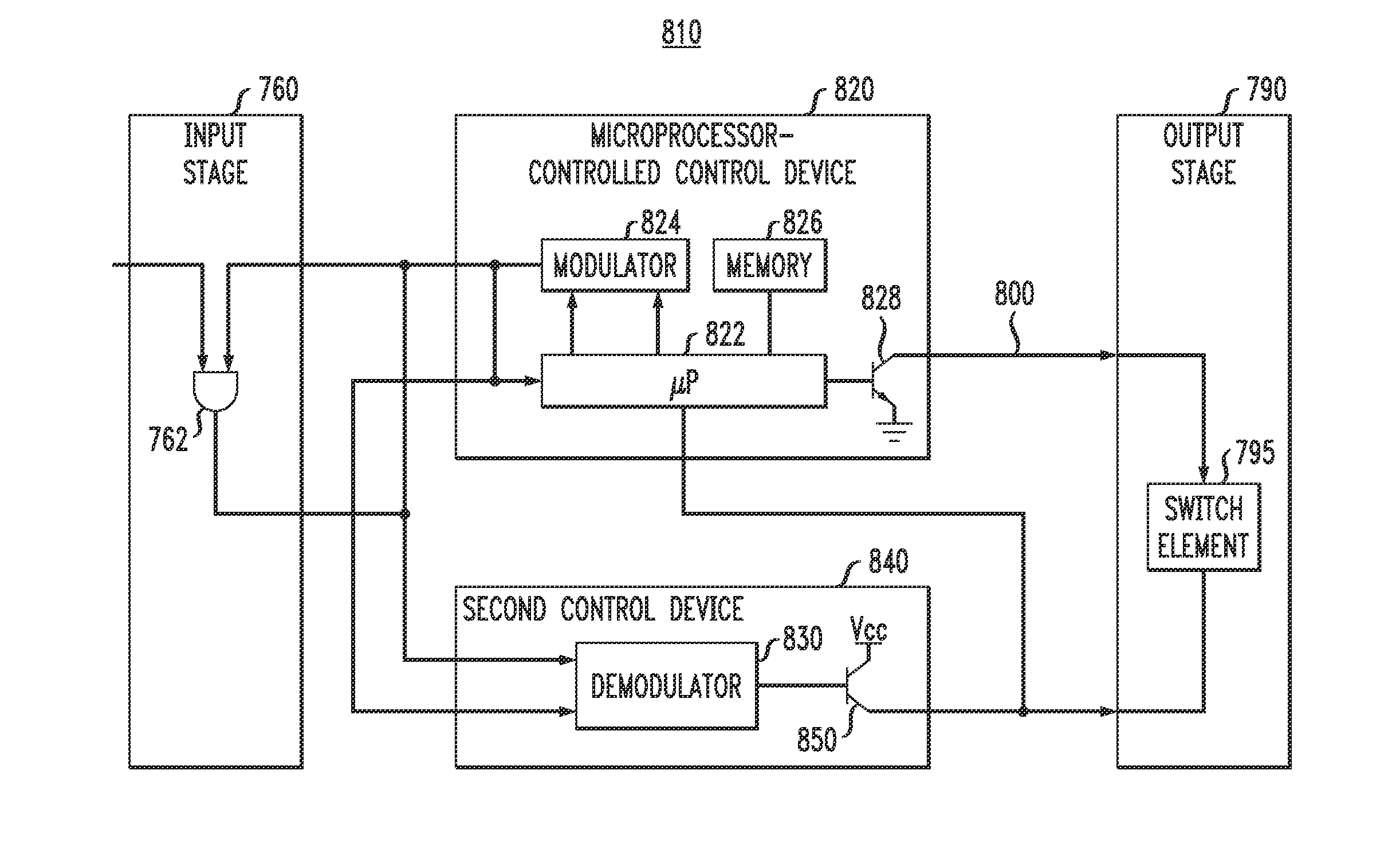
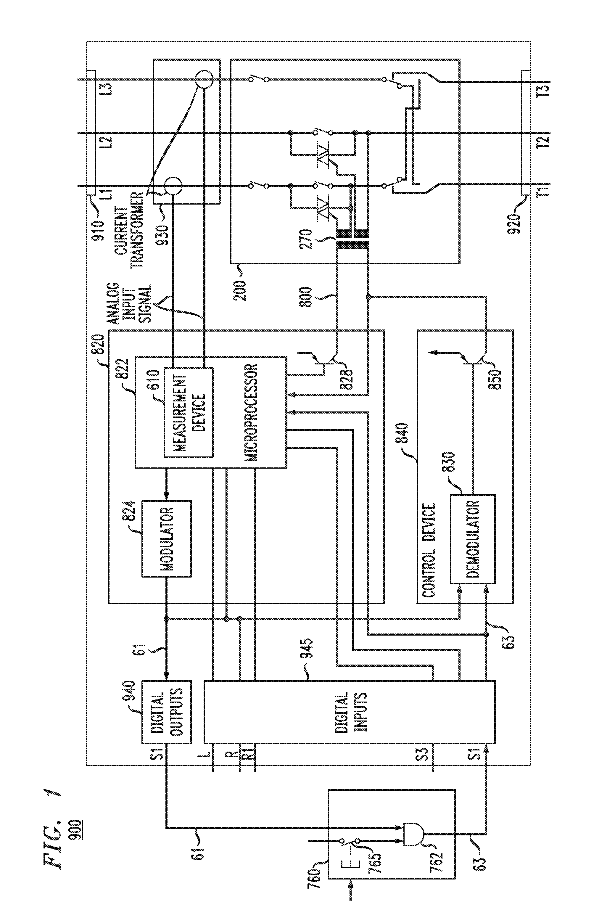
[0095]In FIG. 1, the block circuit diagram of an example safety switching device 900 is shown, whose components can be accommodated in a housing. The safety switching device 900 has a first connection device 910, by means of which the safety switching device 900 can be connected, for example, to a three-phase power supply network (not shown). The three input wires connected to the power supply network are designated in FIG. 1 with L1, L2, and L3. The three wires L1, L2, and L3 are connected to a power amplifier 200, whose three output-side wires are designated T1, T2, and T3. The three output-side wires are connected to a second connection device 920, to which a safety-related device, for example, a three-phase-current motor, can be connected. It is conceivable that several safety-related devices, e.g., single-phase or multiple-phase drives can also be connected to the safety switching device 900. Accordingly, the power amplifier that is used can have a single-phase or multiple-phas...


PUM


Abstract

A safety switching device, with which a safety-related device, can be set into a safe state. The safety switching device has a microprocessor or microcontroller, which can set an electric drive to be protected into a safe state both if an emergency circuit breaker, protective door switch, and / or two-hand switch is activated and also if there is faulty operation of the safety-related device or electric drive. For this purpose, the microprocessor is implemented such that it can determine from at least one analog signal to be measured whether a predetermined parameter lies outside a predetermined operating range. In addition, the microprocessor can be a component of a safety device which is constructed for multiple-channel control of a safety-related electric drive. In this way, the safety switching device can respond to several safety functions independent of each other in order to set an electric drive into a safe state.

Description

CROSS-REFERENCE TO RELATED APPLICATIONS[0001]This application claims priority of U.S. patent application Ser. No. 11 / 915,326 with a U.S. filing date of May 6, 2008, which in turn claims priority to German Application Number 10 2005 036 777.1 filed on Aug. 2, 2005, German Application Number 10 2005 045 753.3 filed on Sep. 23, 2005, and German Application Number 10 2006 001 805.2 filed on Jan. 12, 2006.[0002]Furthermore, U.S. patent application Ser. No. 11 / 915,326 is incorporated herein by reference.FIELD OF THE INVENTION[0003]The invention relates to a safety switching device, with which a safety-related device, preferably an electric drive, can be set to a safe state. Furthermore, the invention relates to a three-phase power amplifier for driving at least one load, a measurement device for measuring a periodic analog signal, whose amplitude can lie outside a preset operating range, and also a safety device for multi-channel control of a safety-related device, which are all together ...

Claims


Application Information

Patent Timeline
Patent Type & Authority Applications(United States)
IPC IPC(8): G01R31/316
CPCG05B9/02H01H47/002H03M1/12H02P23/0072H01H9/542H01H51/005H03M1/207H02P23/24
Inventor KORREK, ANDRE
Owner PHOENIX CONTACT GMBH & CO KG
Why Eureka
Try Eureka