Network distributed packet-based synchronization

a technology of packet synchronization and network distributed packets, applied in the field of clock synchronization, can solve the problems of affecting the synchronization of messages in the communication network

Active Publication Date: 2012-11-29
MICROSEMI STORAGE SOLUTIONS
View PDF5 Cites 26 Cited by
  • Summary
  • Abstract
  • Description
  • Claims
  • Application Information

AI Technical Summary

Problems solved by technology

Any errors in handling the synchronization messages may be detrimental to accurate clock synchronization and the harm may be cumulative over multiple network devices.
Furthermore, some portions of a communication network may not be equipped to handle synchronization messages.

Method used


Image

  • Network distributed packet-based synchronization
  • Network distributed packet-based synchronization
  • Network distributed packet-based synchronization

Examples


Embodiment Construction

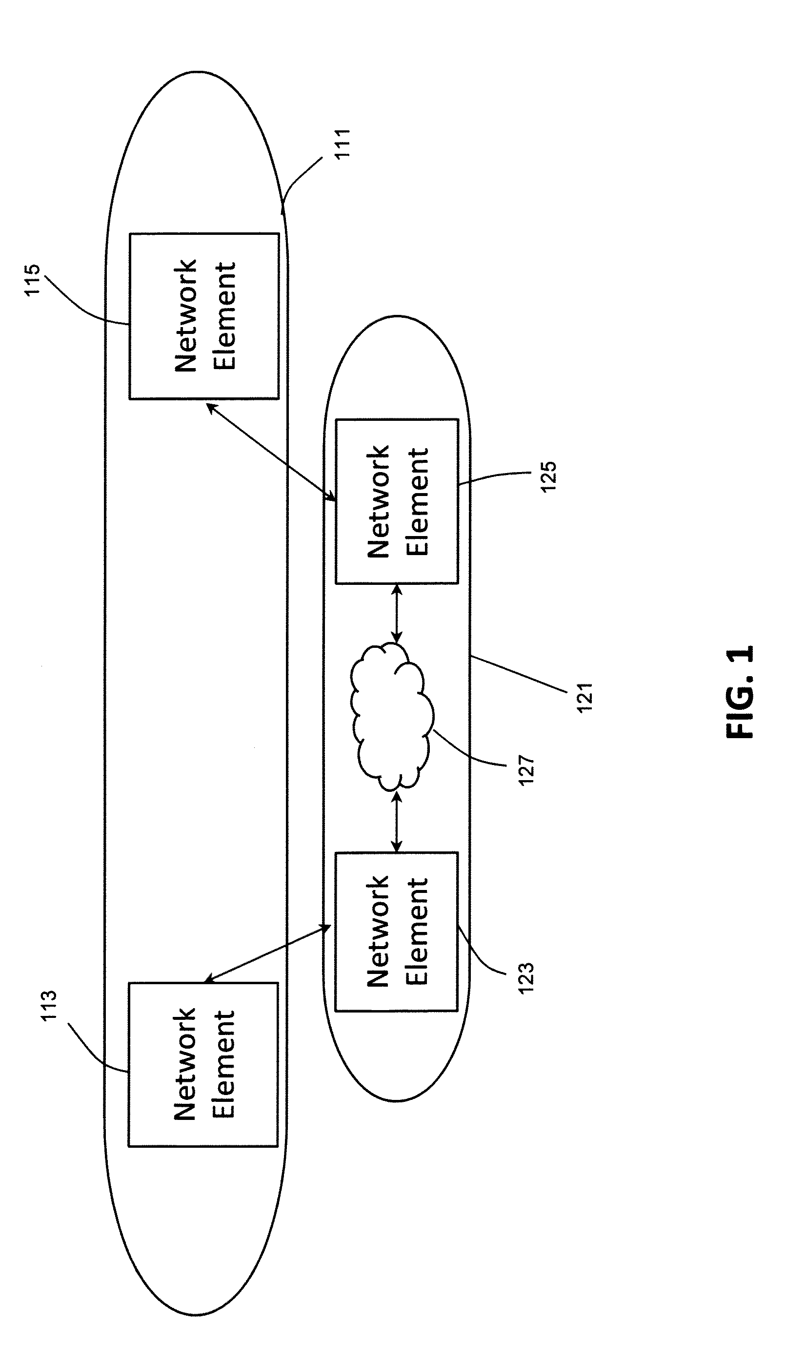
[0017]FIG. 1 is a block diagram of communication networks in accordance with aspects of the invention. The communication networks include a first network device 113 and a second network device 115 that operate in a first network 111 or network domain. The network devices may be, for example, routers. The network devices may also be a combination of devices managed as a network element. The first network device 113, the second network device 115, and additional devices that may be in the first network 111 use a synchronization protocol such as PTP to synchronize clocks at the various devices. The synchronized clocks provide matching time of day and frequency at the synchronized devices. For example, the first network device 113 may serve as a master clock with the second network device 115 having a clock slaved to the master clock. The first network device 113 and the second network device 115 communicate through a second communication network 121. As shown in FIG. 1, the first netwo...


PUM


Abstract

A transparent clock may be provided between edge nodes of a non-precision time protocol network, with an arrival time of a packet at an edge of the non-precision time protocol network carried in a reserved field of a packet.

Description

CROSS REFERENCE TO RELATED APPLICATIONS[0001]This application claims the benefit of U.S. Provisional Application No. 61 / 485,090, filed on May 11, 2011, the disclosure of which is incorporated herein by reference.BACKGROUND OF THE INVENTION[0002]The present invention relates generally to synchronization of clocks and, more particularly, to synchronization of clocks in a packet-switched communication network.[0003]It may be advantageous in a networked system for devices in the network to have a common time base. The common time base may be used, for example, to trigger coordinated measurement instances in a network of sensors or to coordinate actions of controllers in an industrial system. In addition to sensors and controllers, the system may include computers and communication devices, such as routers.[0004]The communications industry has developed several standards for use in synchronizing clocks, for example, the Network Time Protocol (NTP), ITU-T Y.1731, and the Precision Time Pr...

Claims


Application Information

Patent Timeline
Patent Type & Authority Applications(United States)
IPC IPC(8): H04J3/06
CPCH04J3/0667H04J3/0697H04J3/0673
Inventor JOERGENSEN, THOMAS KIRKEGAARD
Owner MICROSEMI STORAGE SOLUTIONS
Why Eureka
Try Eureka