
Rotatable solar panel assemblies

a solar panel and assembly technology, applied in the direction of heat collector mounting/support, electrochemical generators, lighting and heating apparatus, etc., can solve the problems of limited prior art solar panel exposure, disadvantageous particular design strategies, and inability to efficiently capture sunligh

Inactive Publication Date: 2012-12-06
BRUNEAU STEVEN GRANT
View PDF0 Cites 9 Cited by
  • Summary
  • Abstract
  • Description
  • Claims
  • Application Information

AI Technical Summary

Benefits of technology

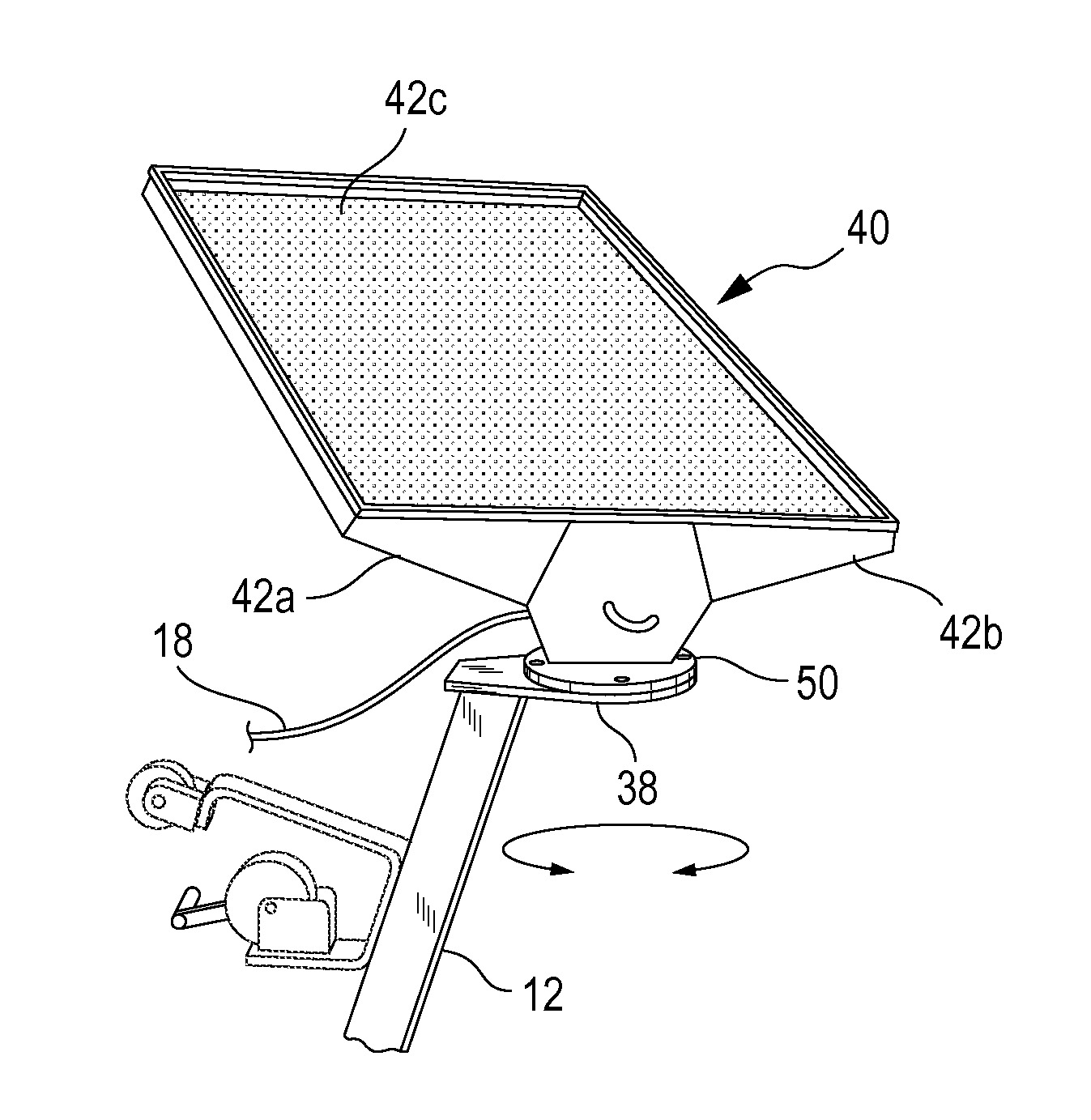
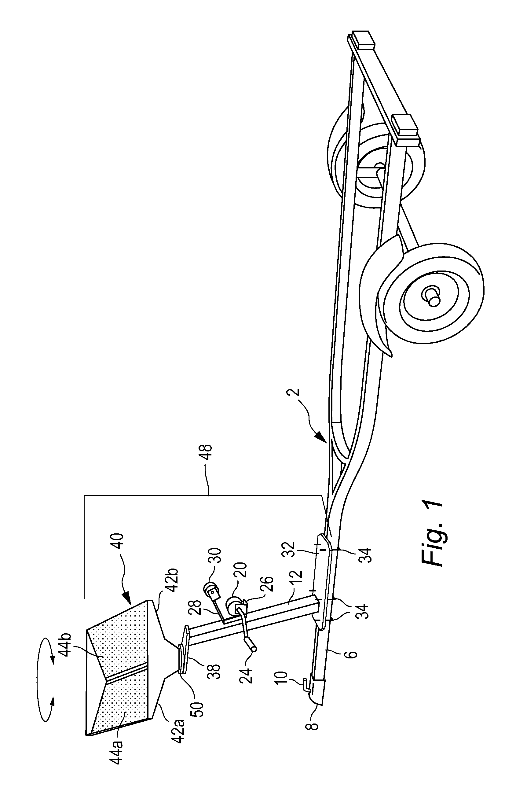
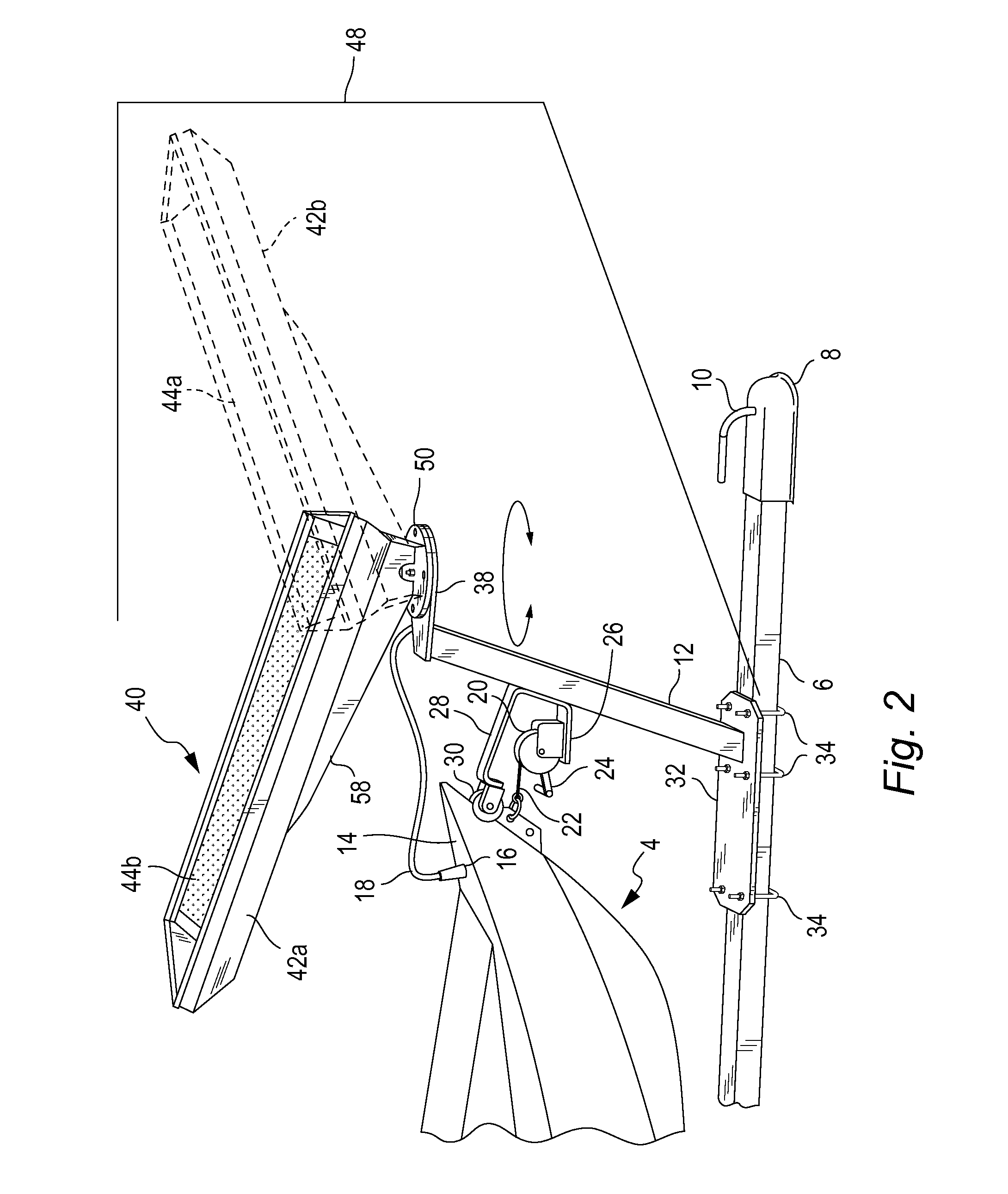
"The patent text describes solar panel assemblies for attachment to a boat trailer and a solar panel housing assembly. The solar panel assembly includes a base plate and a support stanchion for holding a solar panel. The solar panel housing is designed to rotate around a mount on a support structure, allowing for maximum sun exposure. The technical effects of the patent text include improved solar energy utilization and flexibility in installation options."

Problems solved by technology

This particular design strategy is disadvantageous for several reasons.
Firstly, the solar panels on these vehicles are stationary as opposed to rotatable or otherwise adjustable.
Their immobility prohibits efficient capture of sunlight.
Furthermore, the solar panels are only configured to allow charging of the vehicles they are positioned on, as opposed to additional vehicles.
Similarly, prior art solar panel exposure is limited to the particular parking limitations where the trailer is positioned, such that if it is parked under shade or cover, the solar panel cannot be adjusted to capture sunlight efficiently.
Additional problems with current solar panel housing designs is that they don't alleviate the stresses incurred from traveling or inclement environments, such as high winds or water turbulence.
Still further problems with the prior art is that heat is not dissipated from working solar panels efficiently.

Method used


Image

  • Rotatable solar panel assemblies
  • Rotatable solar panel assemblies
  • Rotatable solar panel assemblies

Examples


Embodiment Construction

[0025]Embodiments of the present invention are described below. It is, however, expressly noted that the present invention is not limited to these embodiments, but rather the intention is that modifications that are apparent to the person skilled in the art and equivalents thereof are also included.

[0026]While the majority of the description below is directed to solar panel housings on boat trailers, additional preferred embodiments are directed to rotatable solar panel housings mounted on any suitable vehicle, trailer, machine, or structure, non-exclusively including, military vehicles, construction vehicle, road signs, boats, watercraft, car trailers, residential and commercial buildings, and the like.

[0027]FIG. 1 shows a boat trailer 2 configured to receive and release a watercraft through its back end and releasably couple to a towing vehicle with its front end. More specifically the boat trailer 2 can include a tongue 6 having a hitch coupler 8 and hitching lock 10 for coupling...


PUM


Abstract

Rotatable solar panel assemblies herein are configured to couple to a boat trailer, or other vehicles and structures in order to charge a battery in a boat secured on top of the trailer or to otherwise provide power to vehicles or structures. The solar panel assemblies can be configured to have means for 360 rotation to allow efficient sunlight capture and to allow for a more aerodynamic profile when the trailer is being towed. The assemblies herein include a solar panel housing that can include downwardly slanting sides to protect the one or more solar panels mounted within the housing from road debris, or other hazards.

Description

CROSS-REFERENCE TO RELATED APPLICATIONS[0001]This application claims priority to and is a continuation-in-part to co-pending U.S. application Ser. No. 13 / 013,675, entitled “Solar Panel Assemblies for Attachment to a Boat Trailer”, filed Jan. 25, 2011 which claims priority to U.S. Provisional Application 61 / 336,767, filed on Jan. 26, 2010 which is expressly incorporated herein in its entirety.FIELD OF THE INVENTION[0002]The embodiments herein relate to rotatable solar panel assemblies which can be configured to be attached to a boat trailer, boats, other vehicles, machines, and structures such as houses and buildings. More specifically, the teachings herein can be used to charge a battery operated watercraft coupled to and positioned on top of the boat trailer.BACKGROUND[0003]Watercrafts have utilized solar energy to either fully power or supplement the boat's battery. See for example, U.S. Pat. Nos. 7,047,902, to Little, 6,805,064 to Andersen, and 6,000,353 to De Leu. As the above-l...

Claims


Application Information

Patent Timeline
Patent Type & Authority Applications(United States)
IPC IPC(8): H01L31/048
CPCB60P3/10F24J2/523F24J2/5245H02S20/00H01M10/465Y02E10/47Y02E10/50F24J2/5406H02S20/30F24S25/61F24S30/422F24S25/10Y02E60/10
Inventor BRUNEAU, STEVEN GRANT
Owner BRUNEAU STEVEN GRANT
Learn More