

Electronic apparatus
a technology of electronic equipment and input operation, applied in the field of electronic equipment, can solve the problems of significant inconvenience in input operation using certain functions, and achieve the effect of reducing the possibility
- Summary
- Abstract
- Description
- Claims
- Application Information
AI Technical Summary
Benefits of technology
Problems solved by technology
Method used
Image

Examples
first embodiment
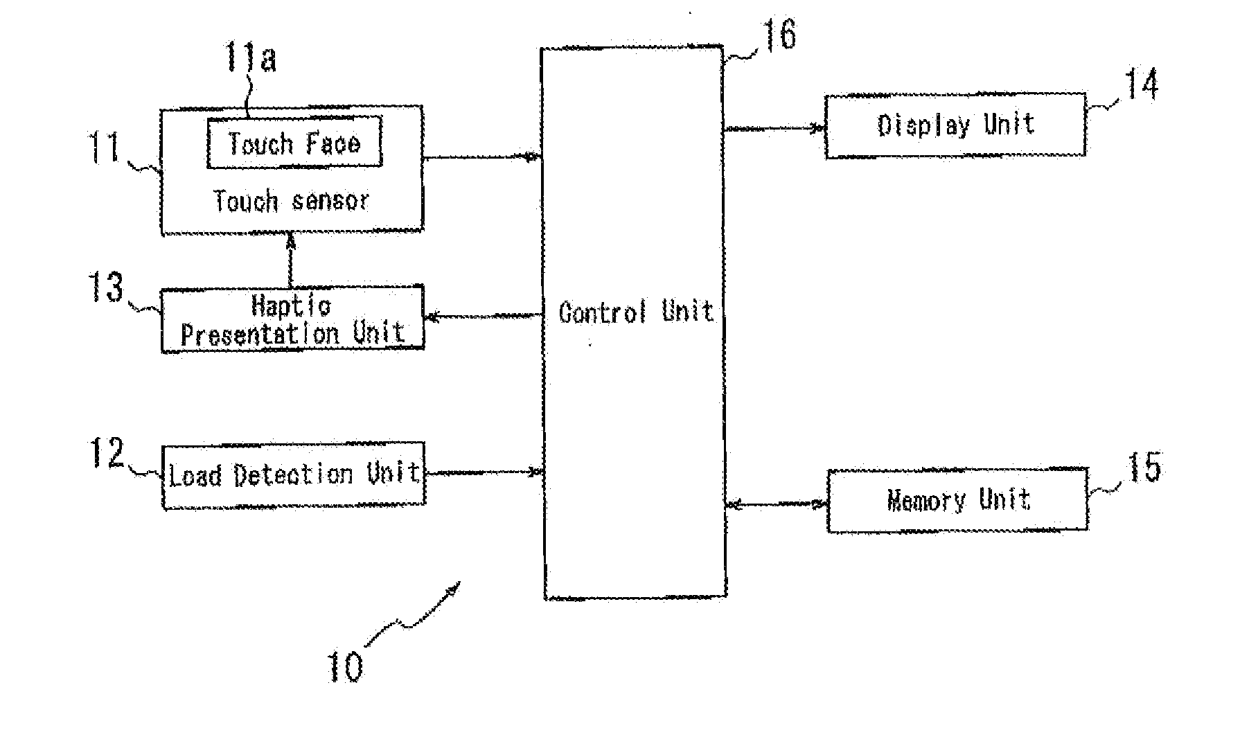
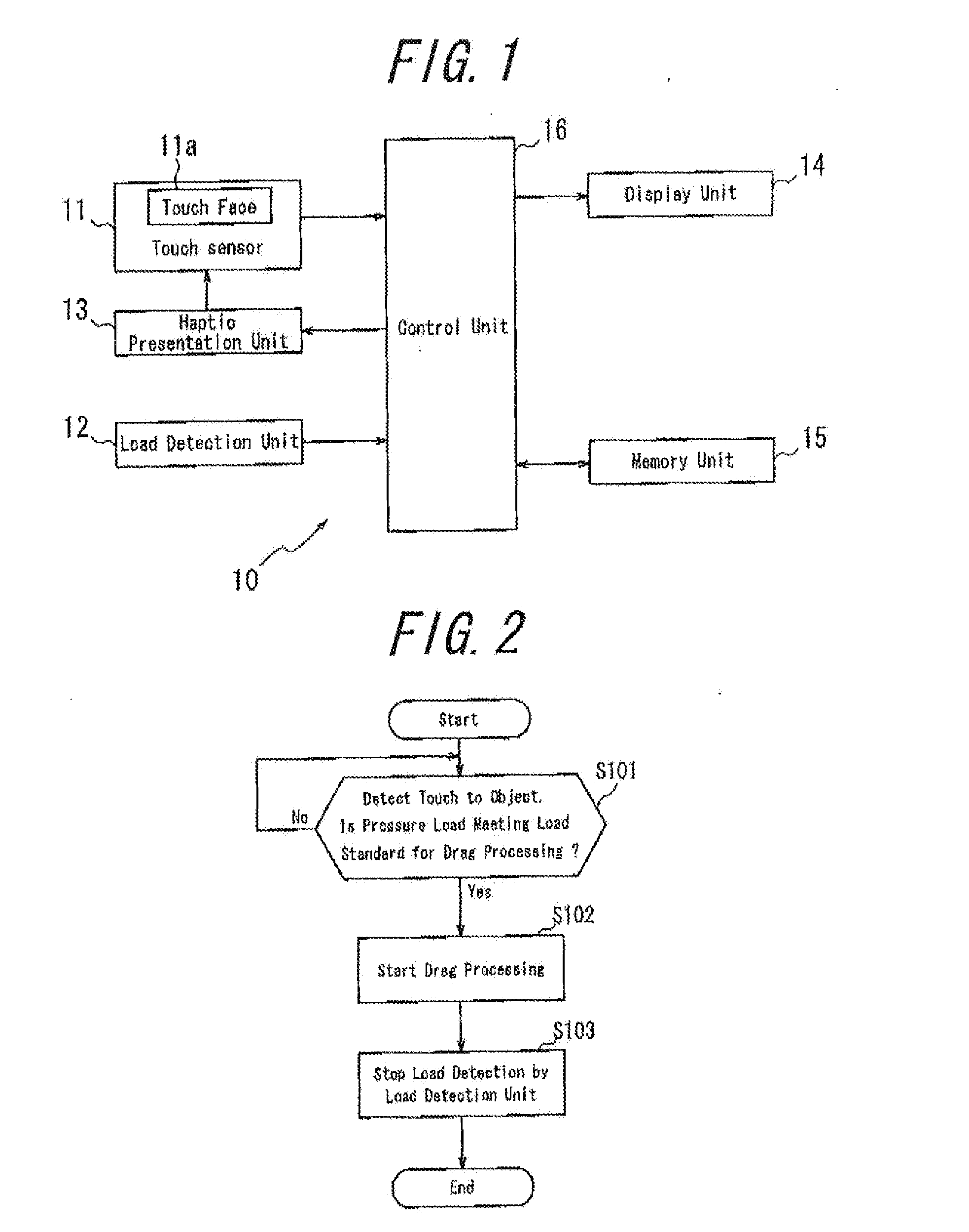
[0031]FIG. 1 is a functional block diagram of an electronic apparatus 10 according to the embodiment of the present invention. As shown in FIG. 1, the electronic apparatus 10 has a touch sensor 11, a load detection unit 12, a haptic presentation unit 13, a display unit 14, a memory unit 15 and a control unit 16 for controlling overall operations.
[0032]The touch sensor 11 detects a touch by a touch object such as a finger or a stylus to a touch face 11a thereof. The touch sensor 11 may be of resistive type, capacitance type, or optical type and is arranged on the display unit 14. The load detection unit 12 detects a pressure load of a pressure input, and for example, detects a pressure load on the touch face 11a of the touch sensor 11. The load detection unit 12 may include an element reactive to a load such as, for example, a strain gauge sensor or a piezoelectric element. The haptic presentation unit 13 vibrates the touch sensor 11 and may include, for example, a piezoelectric elem...
second embodiment
[0042]Next, the electronic apparatus 10 according to a second embodiment of the present invention will be described. The electronic apparatus 10 according to the second embodiment may have the same configuration as that of the first embodiment but with different processing and operations by the control unit 16. Accordingly, the same explanation and description of the same effects as those of the first embodiment are appropriately omitted.
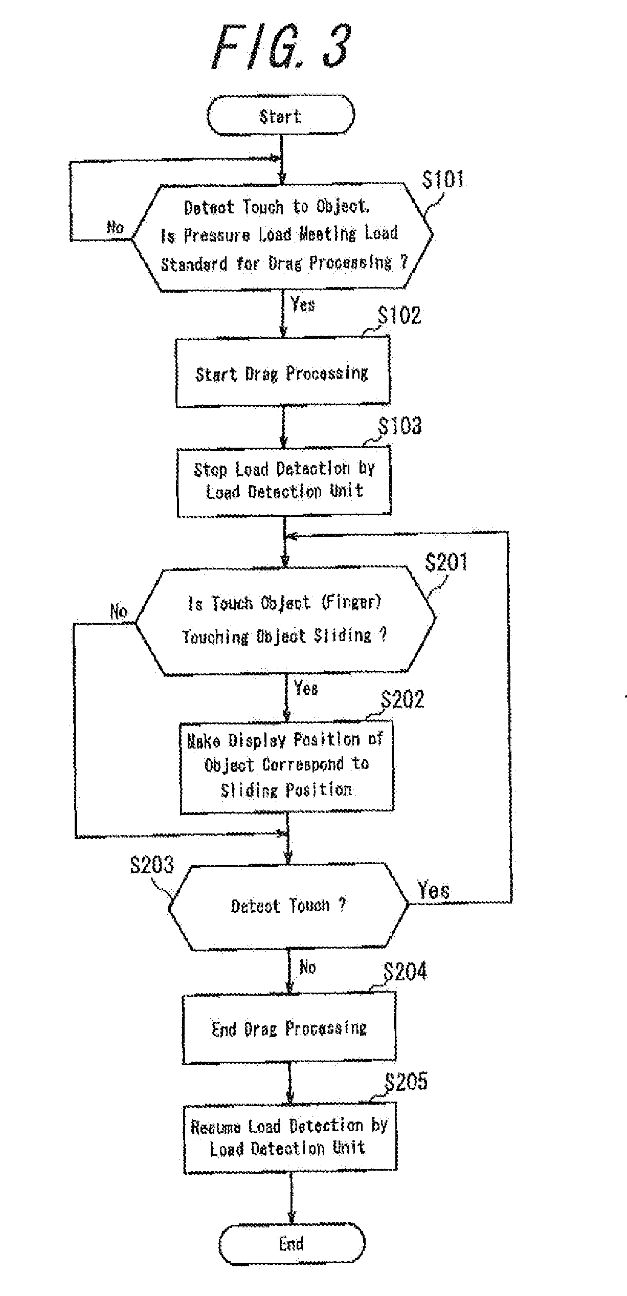
[0043]Input processing according to the second embodiment will be described with reference to a flowchart in FIG; 3. Steps for the same processing as those in FIG. 2 are given the same step numbers.
[0044]The control unit 16, after step S103, determines whether the touch object such as the finger touching an object is sliding on the touch face 11a of the touch sensor 11 (step S201). If it determines that the touch object such as the finger is sliding on the touch face 11a of the touch sensor 11, the control unit 16 controls such that the object displ...
third embodiment
[0047]Now, an electronic apparatus 10 according to a third embodiment of the present invention will be described. The electronic apparatus 10 according to the third embodiment may have the same configuration as that of the first embodiment but with different processing and operations by the control unit 16. Accordingly, the same explanation and description of the same effect as those of the first embodiment are appropriately omitted.
[0048]Input processing according to the third embodiment will be described with reference to a flowchart in FIG. 4. According to the third embodiment, the control unit 16 first detects a touch to an object displayed on the display unit 14 by the touch sensor 11 and also determines whether a pressure load detected by the load detection unit 12 meets the load standard for the drag processing (referred to as the “drag processing load standard”) (step S301). If it detects a touch to the object by the touch sensor 11 and also determines that the pressure load...
PUM
 Abstract
Description
Claims
Application Information