
System and method for controlling unmanned aerial vehicle

a technology for unmanned aerial vehicles and control systems, applied in process and machine control, television systems, instruments, etc., can solve the problems that many uavs cannot automatically recognize and track people appearing in the areas being monitored

Inactive Publication Date: 2012-12-06
HON HAI PRECISION IND CO LTD
View PDF4 Cites 85 Cited by
  • Summary
  • Abstract
  • Description
  • Claims
  • Application Information

AI Technical Summary

Benefits of technology

The present patent relates to a system and method for controlling an unmanned aerial vehicle (UAV) in flight. The technical effect of this patent is to enable the UAV to automatically recognize and track people in the areas it is monitoring, using a figure detection method and adjusting the tilt angle and focus of the lens accordingly to provide a better view of the person. This system and method can improve the efficiency and safety of the UAV by automatically identifying and tracking people in real-time, allowing for better situational awareness and response capabilities.

Problems solved by technology

However, at present, many UAV cannot automatically recognize and track people appearing in the areas being monitored.

Method used


Image

  • System and method for controlling unmanned aerial vehicle
  • System and method for controlling unmanned aerial vehicle
  • System and method for controlling unmanned aerial vehicle

Examples


Embodiment Construction

[0008]The present disclosure, including the accompanying drawings, is illustrated by way of examples and not by way of limitation. It should be noted that references to “an” or “one” embodiment in this disclosure are not necessarily to the same embodiment, and such references mean at least one.

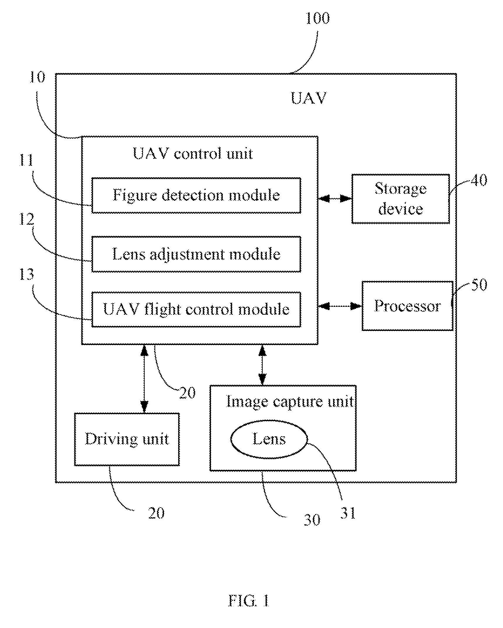
[0009]FIG. 1 is a block diagram of one embodiment of an unmanned aerial vehicle (UAV) 100. In this one embodiment, the UAV 100 includes a UAV control unit 10, a driving unit 20, an image capture unit 30, a storage device 40, and a processor 50. The image capture unit 30 is a video camera having night viewing capabilities and pan / tilt / zoom functions, and is used to capture one or more images of one or more scenes (hereinafter, “scene image”) of a monitored area. As shown in FIG. 1, the image capture unit 30 includes a lens 31. The UAV control unit 10 analyzes the scene image to detect an image of a person (hereinafter, “figure image”) from the scene image, determines location information of the...


PUM


Abstract

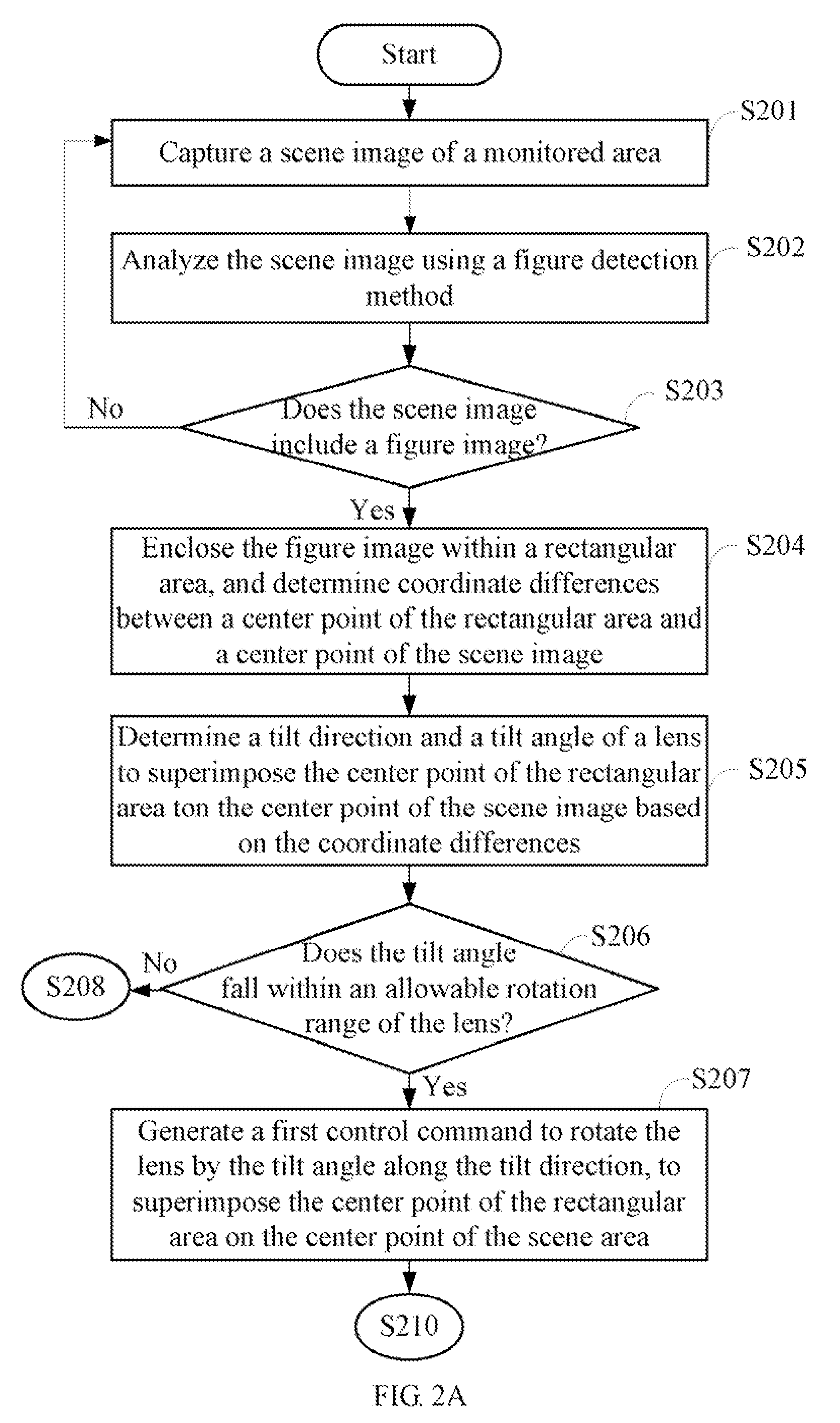
An unmanned aerial vehicle (UAV) includes a driving unit and a control unit. The control unit detects a human figure in an image of a scene of a monitored area, determines coordinate differences between the scene image's center and the figure image's center, and determines a tilt direction and a tilt angle of a lens of the image capture unit based on the coordinate differences. If the tilt angle falls within an allowable rotation range of the lens, the control unit controls the driving unit to directly rotate the lens by the tilt angle along the tilt direction. Otherwise, the control unit controls the driving unit to rotate the lens by a threshold angle along the tilt direction, and further controls the driving unit to adjust a flight orientation and a flight height of the UAV until the figure image's center superposes the scene image's center.

Description

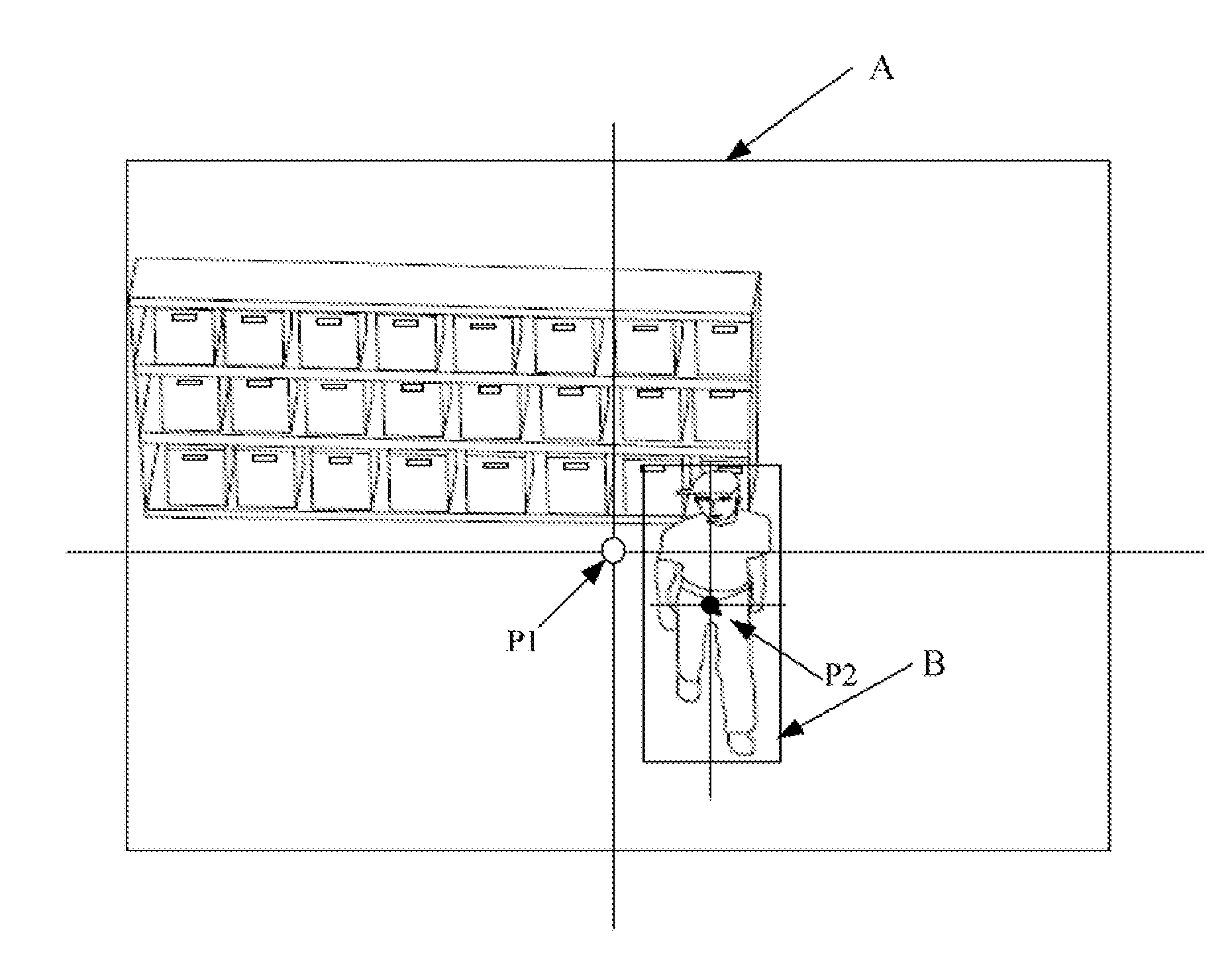
BACKGROUND[0001]1. Technical Field[0002]The embodiments of the present disclosure relate to aircraft control systems and methods, and more particularly to a system and method for controlling an unmanned aerial vehicle (UAV) in flight.[0003]2. Description of Related Art[0004]An unmanned aerial vehicle (UAV), also known as an unmanned aircraft system (UAS) or a remotely piloted aircraft (RPA), is a vehicle which is guided and / or functions under control of a remote navigator. The UAV is often preferred for monitoring desolate or dangerous areas. However, at present, many UAV cannot automatically recognize and track people appearing in the areas being monitored.BRIEF DESCRIPTION OF THE DRAWINGS[0005]FIG. 1 is a block diagram of one embodiment of an unmanned aerial vehicle (UAV) including a UAV control unit.[0006]FIG. 2A and FIG. 2B are flowcharts of one embodiment of a UAV controlling method.[0007]FIG. 3 and FIG. 4 are images of a scene captured by an image capture unit within the UAV.D...

Claims


Application Information

Patent Timeline
Patent Type & Authority Applications(United States)
IPC IPC(8): H04N7/18
CPCG08G5/0069H04N5/23219G05D1/101G05D1/0094H04N5/232H04N23/67H04N23/635H04N23/695
Inventor LEE, HOU-HSIENLEE, CHANG-JUNGLO, CHIH-PING
Owner HON HAI PRECISION IND CO LTD
Learn More