Boiling refrigerant type cooling system

a refrigerant type, cooling system technology, applied in domestic cooling apparatus, semiconductor/solid-state device details, applications, etc., can solve problems such as device breakage, failure of semiconductor devices, and inability to maintain performance, and achieve stable boiling start and bubble generation in the groove part.

Inactive Publication Date: 2012-12-13
HITACHI LTD
View PDF8 Cites 13 Cited by
  • Summary
  • Abstract
  • Description
  • Claims
  • Application Information

AI Technical Summary

Benefits of technology

[0016]In the boiling refrigerant type cooling system according to the present invention, since the thickness of the base in the groove is thinned by the groove added to the boiling heat transfer unit, the temperature of the base in the groove part is higher than its peripheral part, and bubble generation in

Problems solved by technology

However, in the above-described semiconductor device, generally, its performance cannot be maintained at a temperature equal to or higher than a predetermined temperature, and further, the device may be broken in some cases.
When a heat generating body is cooled using the above-described boiling refrigerant type cooling system, there is a problem of overshoot which occurs especially upon start of boiling.
When the overshoot occurs, there is a probability that the temperature is raised beyond a permissible limit of the semi

Method used


Image

  • Boiling refrigerant type cooling system
  • Boiling refrigerant type cooling system
  • Boiling refrigerant type cooling system

Examples


first embodiment

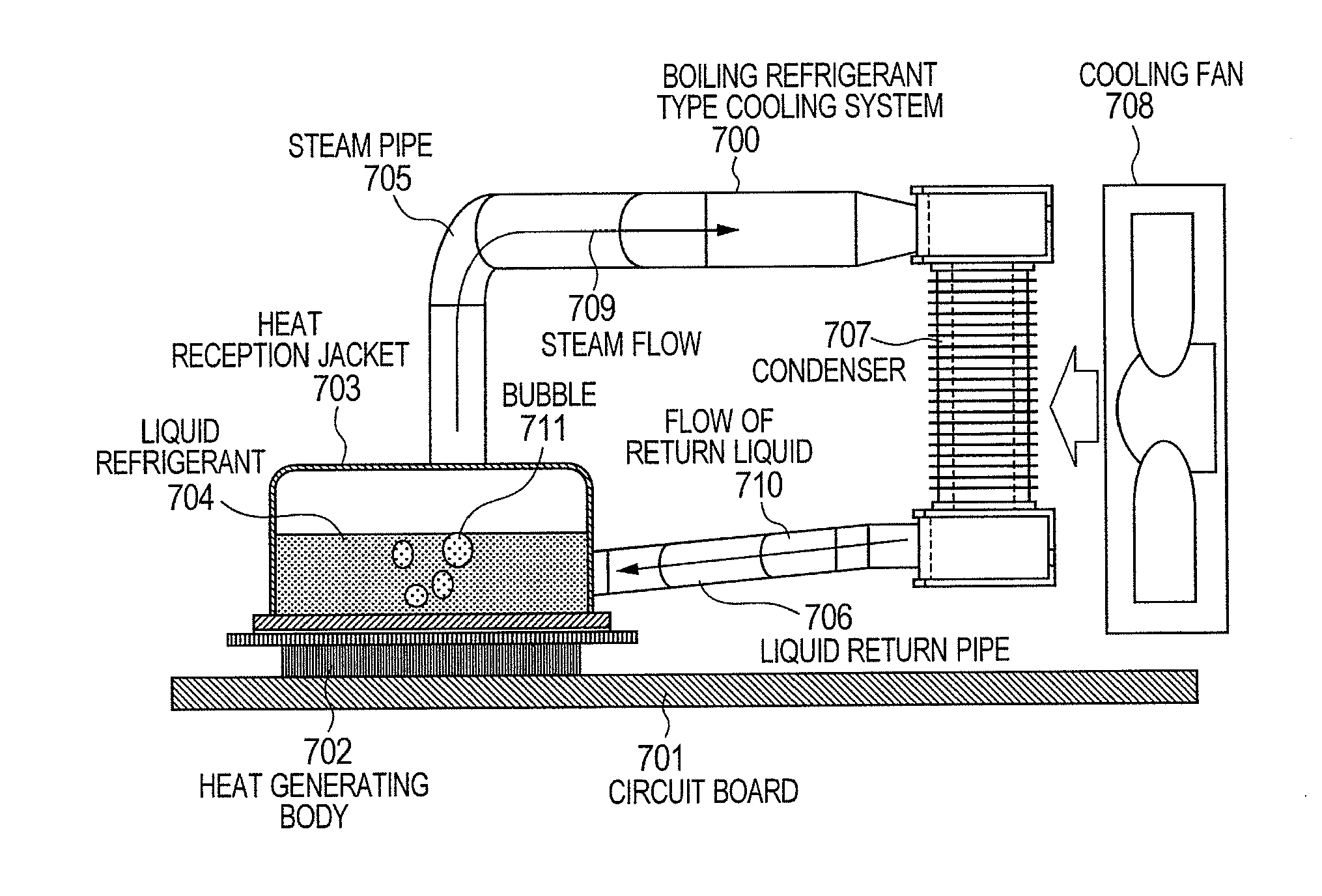
[0033]FIG. 7 shows an entire structure of a boiling refrigerant type cooling system as an embodiment of the present invention. A heat generating body 702 such as a semiconductor device is provided on a circuit board 701. A heat reception jacket 703 having a boiling stabilizing structure according to the present invention is attached to the surface of the heat generating body 702. The heat generating body 702 and the heat reception jacket 703 are in thermal contact with each other. Further, a liquid refrigerant 704 is accommodated inside the heat reception jacket 703, and is connected to a condenser 707 via a steam pipe 705 and a liquid return pipe 706. Further, a cooling fan 708 is placed in a position to send cooling air to the condenser 707.

[0034]In the boiling refrigerant type cooling system 700 having the above structure, heat generated in the heat generating body 702 is transmitted to the heat reception jacket 703. The liquid refrigerant 704 is boiled with the transmitted heat ...

second embodiment

[0047]FIG. 15 shows a structure in a case where the structure of FIG. 7 is provided in plural positions on the circuit board. With respect to three semiconductor devices provided on a circuit board 701, heat reception jackets 703a to 703c are provided. Steam pipes 705a to 705c and liquid return pipes 706a to 706c are connected from the heat reception jackets 703a to 703 to a condenser 707 for heat exchange. The condenser 703 performs heat exchange with respect to the steam sent from the three heat reception jackets 703a to 703c. A cooling fan 708 is provided in the vicinity of the condenser 707 to promote the heat exchange. Further, in the steam pipes 705a to 705c, a sensor to detect steam pressure and steam temperature is provided at the exits on the condenser 707 side, and in the liquid return pipes 706a to 706c, a valve to control a liquid return amount is provided at the entrances on the condenser 707 side. In this case, it is possible to control the liquid return amount by cont...


PUM


Abstract

A boiling refrigerant type cooling system to suppress overshoot upon start of heat generation and realize stable start of boiling. In the boiling refrigerant type cooling system, a metal boiling heat transfer unit has a base in thermal contact with a heat generating body. The boiling heat transfer unit is in contact with a liquid refrigerant. The boiling heat transfer unit has plural parallel tunnels communicating with the outside via holes or gaps under its surface, a groove deeper than a tunnel diameter formed through all the tunnels in an orthogonal direction to the tunnels, and a cover plate on the groove.

Description

INCORPORATION BY REFERENCE[0001]The present application claims priority from Japanese application serial No. 2011-131027, filed on Jun. 13, 2011, the entire contents of which are hereby incorporated by reference into this application.BACKGROUND OF THE INVENTION[0002]The present invention relates to a boiling refrigerant type cooling system preferably applicable to cooling of a heat generating body such as a semiconductor device, and more particularly, to a boiling refrigerant type cooling system to realize stable start of boiling even with respect to a heat generating body with high heat generation density.[0003]In recent years, a semiconductor device such as a central processing unit (CPU) incorporated in electronic devices such as a personal computer or a server has an increasing heat release value due to miniaturization and high integration. However, in the above-described semiconductor device, generally, its performance cannot be maintained at a temperature equal to or higher th...

Claims


Application Information

Patent Timeline
IPC IPC(8): F28D15/02F25B49/00
CPCH01L23/427F25B39/04H05K1/0201H05K7/20318H01L2924/0002H01L2924/00F28D15/046F28F13/187F28D15/0266
Inventor SUZUKI, KAZUAKISATO, SHIGEMASAIDEI, AKIO
Owner HITACHI LTD
Why Eureka
Try Eureka