Electronic device with power button assembly

Inactive Publication Date: 2012-12-13
FU TAI HUA IND SHENZHEN +1
View PDF4 Cites 0 Cited by
  • Summary
  • Abstract
  • Description
  • Claims
  • Application Information

AI Technical Summary

Benefits of technology

[0004]An electronic device is provided with a power button assembly to turn a power supply on or off. The power button assembly may be received in an assembly hole defined in a housing of the electronic device. The power button assembly includes a press button and a printed circuit board (PCB), the PCB includes an electric terminal corresponding to the press button. When the press button is pressed to contact the electric terminal, the power supply turns on or off. In assembling the power button to the electronic device, the press button is received in the assembly hole, and the PCB is positioned on one side of the press button by means of a positioning mechanism to ensure assembly accuracy between the PCB and the press button, thereby the press button effectively electronically contacts the PCB. However, the PCB may be incorrectly positioned in relation to the press button due to insufficient accuracy of the positioning mechanism, thus the power button assembly may malfunction or even break down in use.

Problems solved by technology

However, the PCB may be incorrectly positioned in relation to the press button due to insufficient accuracy of the positioning mechanism, thus the power button assembly may malfunction or even break down in use.

Method used


Image

  • Electronic device with power button assembly
  • Electronic device with power button assembly
  • Electronic device with power button assembly

Examples


Embodiment Construction

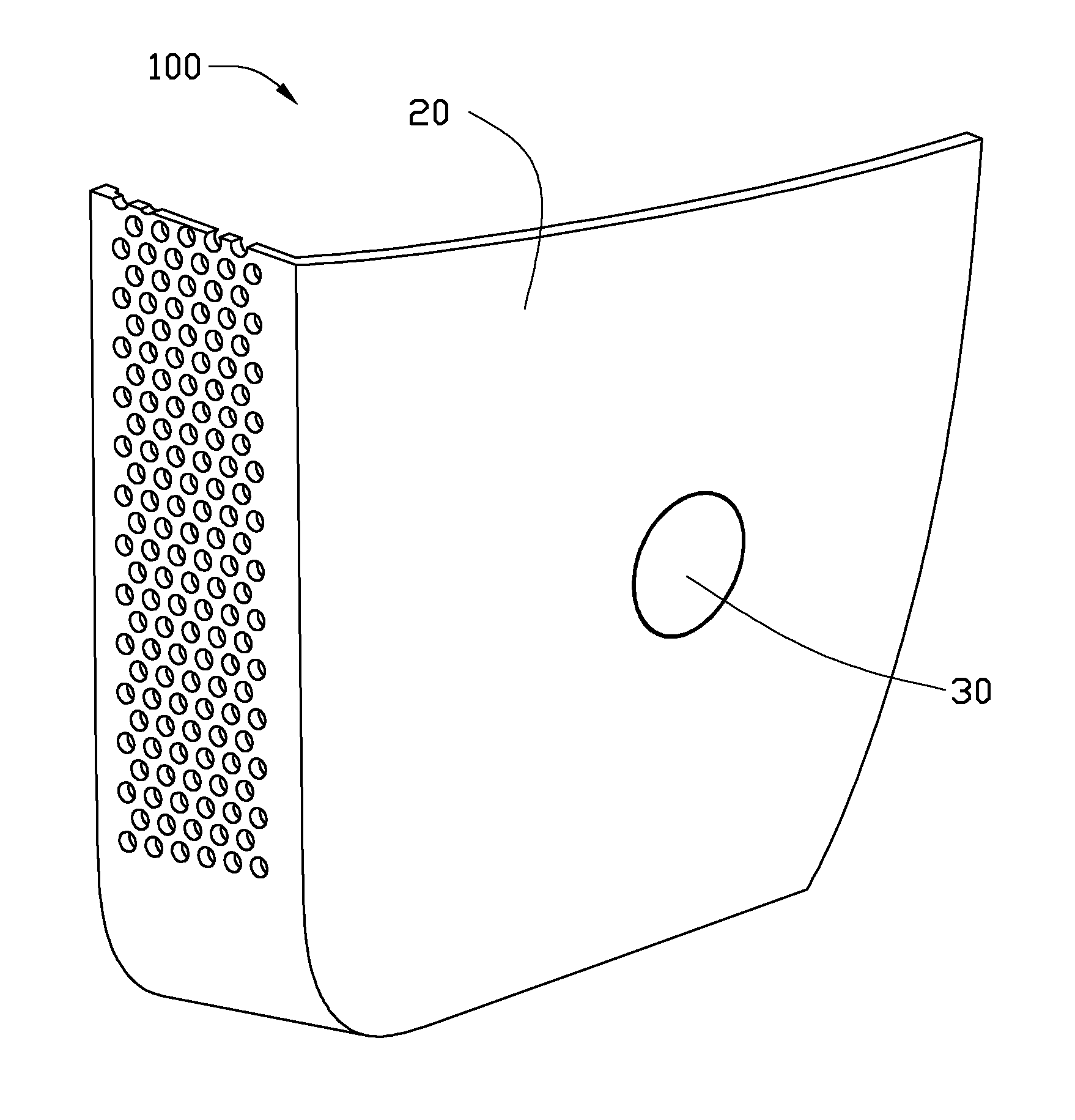
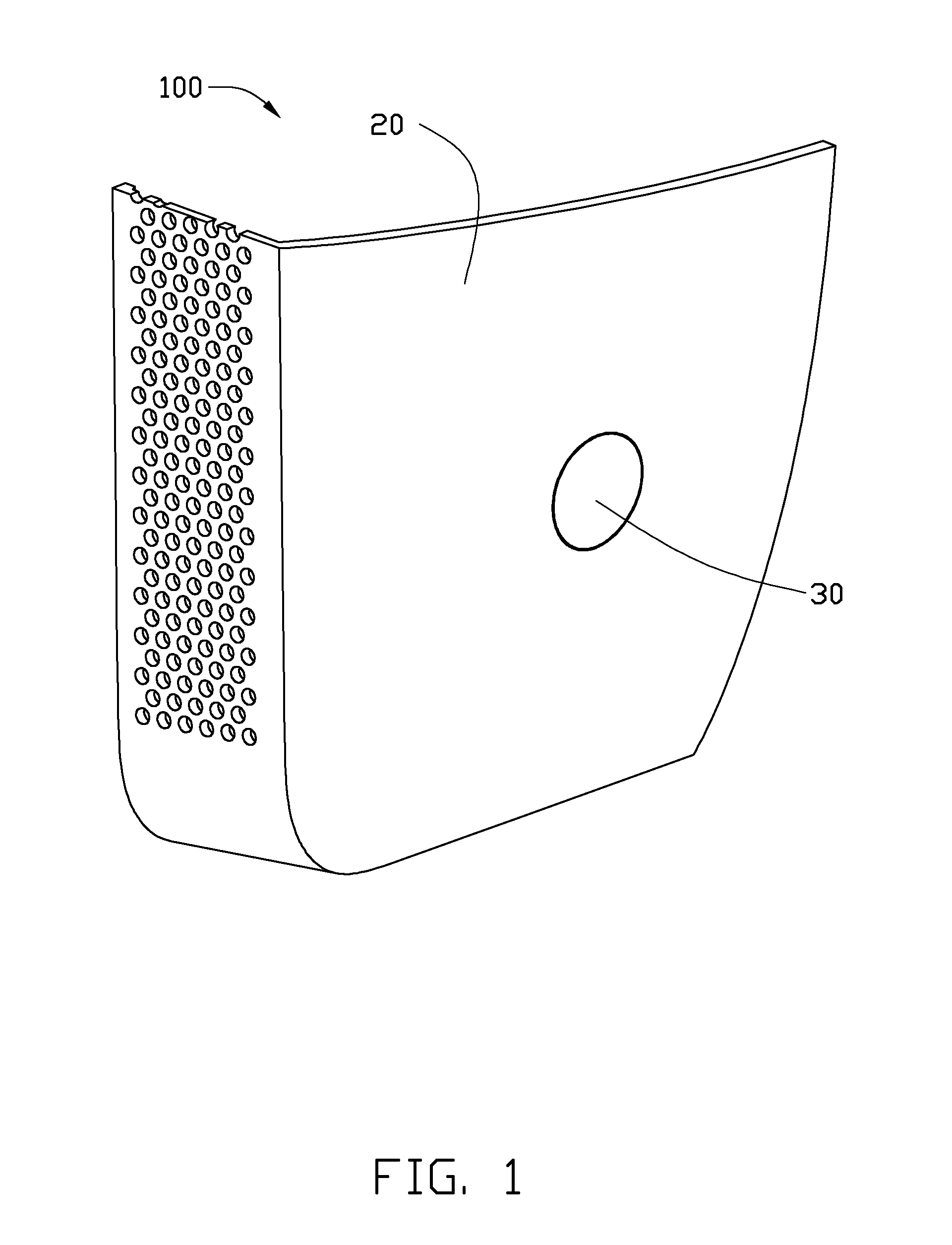
[0014]Referring to FIGS. 1 and 2, one embodiment of an electronic device 100 includes a housing 20 and a power button assembly 30 mounted on the housing 20. The electronic device 100 may be a notebook, a desktop computer, a liquid crystal display or other electronic device capable of employing the power button assembly 30. The electronic device 100 includes various modules for performing specific functions and features. However, for simplicity, only the module related to the power button assembly 30 is described.

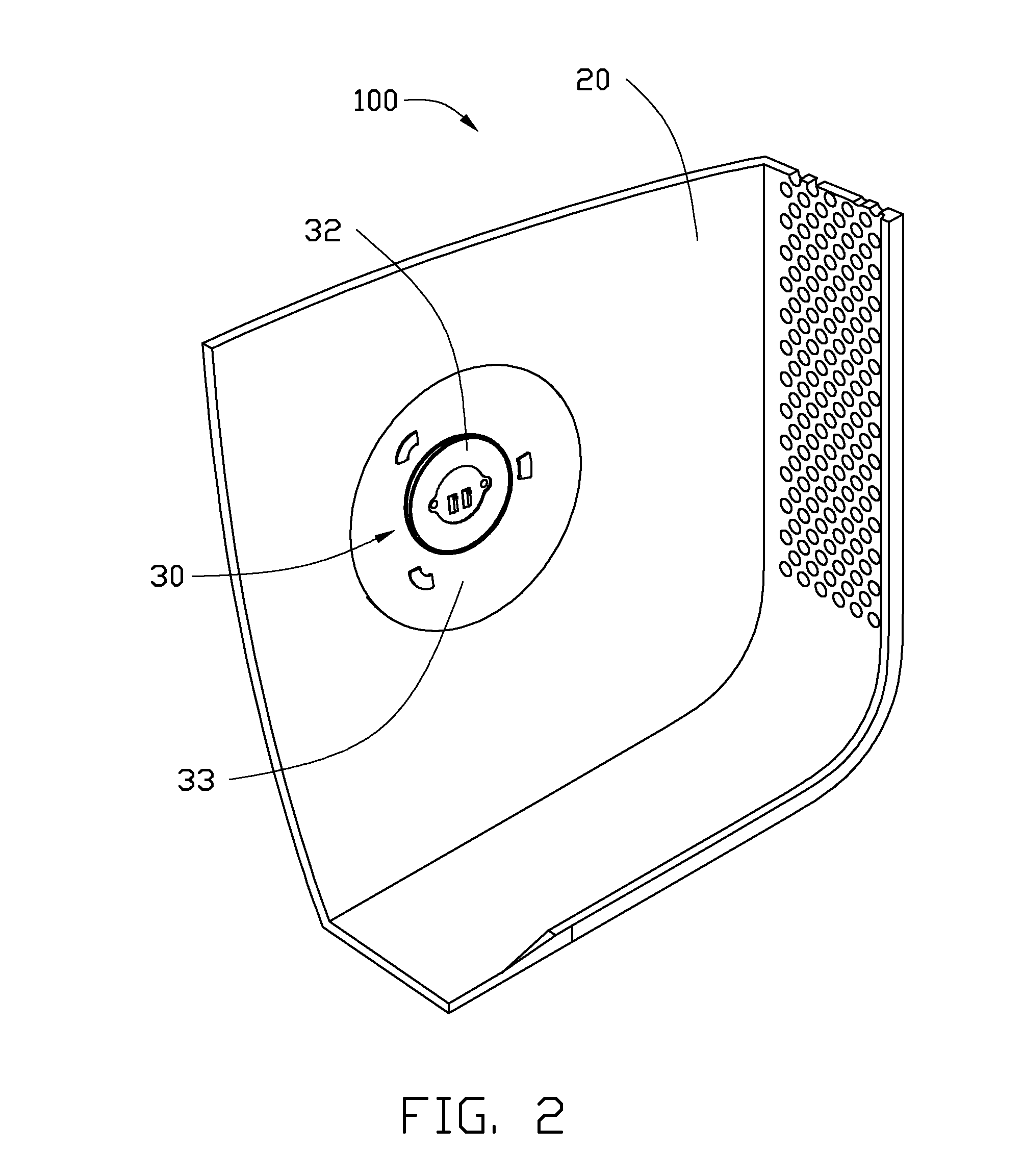
[0015]Referring to FIGS. 3 and 4, the housing 20 defines an assembly hole 21 and an assembly portion 23 around the assembly hole 21. In the illustrated embodiment, the assembly portion 23 is substantially a U-shaped depression defined in the inner surface of the housing 20 around the assembly hole 21. The assembly portion 23 may be of another shape, such as square or rectangular. The assembly portion 23 includes a side wall 231, and the side wall 231 is also substantially U-...


PUM


Abstract

An electronic device includes a housing and a power button assembly mounted on the housing. The housing defines an assembly hole and an assembly portion around the assembly hole, and the assembly portion includes a side wall. The power button assembly includes a pressing button received in the assembly hole, a printed circuit board, and a support plate connected to the printed circuit board. The support plate is fixed on the housing, such that the printed circuit board is positioned opposite the pressing button. The support plate includes a plurality of positioning portions bent towards the printed circuit board along an imaginary outline corresponding to the side wall, respectively, and the positioning portions are inserted in the assembly portion and abut the side wall correspondingly.

Description

BACKGROUND[0001]1. Technical Field[0002]The present disclosure relates generally to electronic devices, particularly, to an electronic device having a power button assembly.[0003]2. Description of Related Art[0004]An electronic device is provided with a power button assembly to turn a power supply on or off. The power button assembly may be received in an assembly hole defined in a housing of the electronic device. The power button assembly includes a press button and a printed circuit board (PCB), the PCB includes an electric terminal corresponding to the press button. When the press button is pressed to contact the electric terminal, the power supply turns on or off. In assembling the power button to the electronic device, the press button is received in the assembly hole, and the PCB is positioned on one side of the press button by means of a positioning mechanism to ensure assembly accuracy between the PCB and the press button, thereby the press button effectively electronically...

Claims


Application Information

Patent Timeline
IPC IPC(8): H01H1/20
CPCH01H13/85H01H2221/002H01H2215/02
Inventor DAI, BIN
Owner FU TAI HUA IND SHENZHEN
Why Eureka
Try Eureka