Assembly method for main shaft with taper hole in end face or with precision requirement for end face and machining tool

An assembly method and end face technology, applied in metal processing equipment, machine tools suitable for grinding workpiece planes, machine tools designed for grinding workpiece rotating surfaces, etc., can solve long assembly period, unqualified spindle precision, uncontrollable, etc. problems, to achieve the effect of shortening the assembly cycle, ensuring assembly accuracy and quality, and facilitating realization

Inactive Publication Date: 2019-04-09
陕西诺贝特自动化科技股份有限公司
View PDF5 Cites 0 Cited by
  • Summary
  • Abstract
  • Description
  • Claims
  • Application Information

AI Technical Summary

Problems solved by technology

However, during the assembly process of the shaft core, bearings, main shaft sleeve, front gland and rear gland, due to the large number of these parts, many unpredictable factors and uncontrollable factors, the degree of freedom of assembly is too large, and the center of the shaft core The line may not be consistent with the center line of the center of rotation after the spindle is installed, resulting in an out-of-tolerance concentricity between the shaft core taper hole and the spindle rotation center or an out-of-tolerance verticality between the shaft core end and the spindle rotation center, resulting in the formation of the spindle during assembly. During the process, it is necessary to repeatedly disassemble and install the bearings outside the shaft core, the inner spacer ring and the outer spacer ring to ensure the installation accuracy
However, the spindle of CNC equipment, especially the shaft core with high-precision taper hole on the end surface or the shaft core with high-precision requirements on the end surface of the shaft core, limits the accuracy of the spindle when assembled into a spindle, especially for high-precision machine tools. The accuracy of the spindle is improved 0.001mm is very, very difficult
Obviously, the machining accuracy of machine tool spindle parts is very high, and often the parts are qualified, but in the process of assembly, the impact of unpredictable factors leads to unqualified spindle accuracy, long assembly period, unable to ensure assembly accuracy and assembly quality, and delay Assembly progress

Method used


Image

  • Assembly method for main shaft with taper hole in end face or with precision requirement for end face and machining tool
  • Assembly method for main shaft with taper hole in end face or with precision requirement for end face and machining tool

Examples


Embodiment Construction

[0028] The present invention provides a method for assembling a spindle with a tapered hole on the end surface or a precision requirement on the end surface. The method for assembling the spindle with a tapered hole on the end surface or a precision requirement on the end surface includes the following steps:

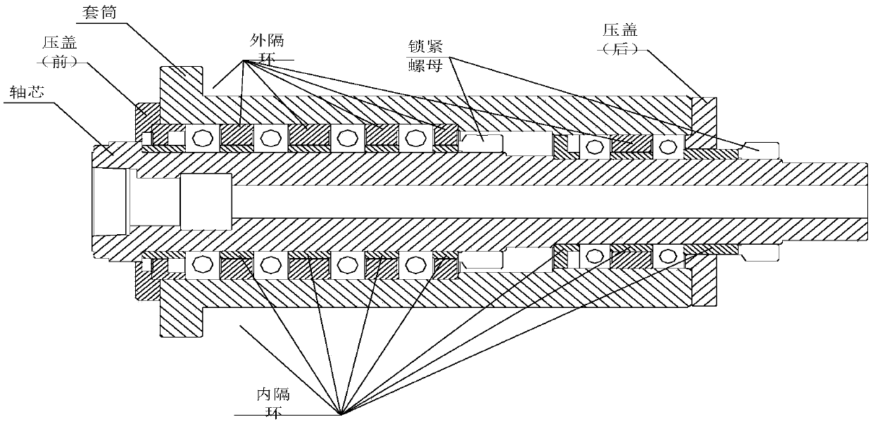
[0029] 1) Set bearings outside the shaft core with axially high-precision tapered holes or axially high-precision end faces, and use inner spacers and outer spacer rings (shaft core, front and rear glands, spindle sleeves, inner and outer spacers can be used if necessary) spacer ring) to limit the inner ring and outer ring of the bearing, set the front gland and rear gland at the ends of the inner spacer ring and the outer spacer ring, and assemble to form the main shaft;

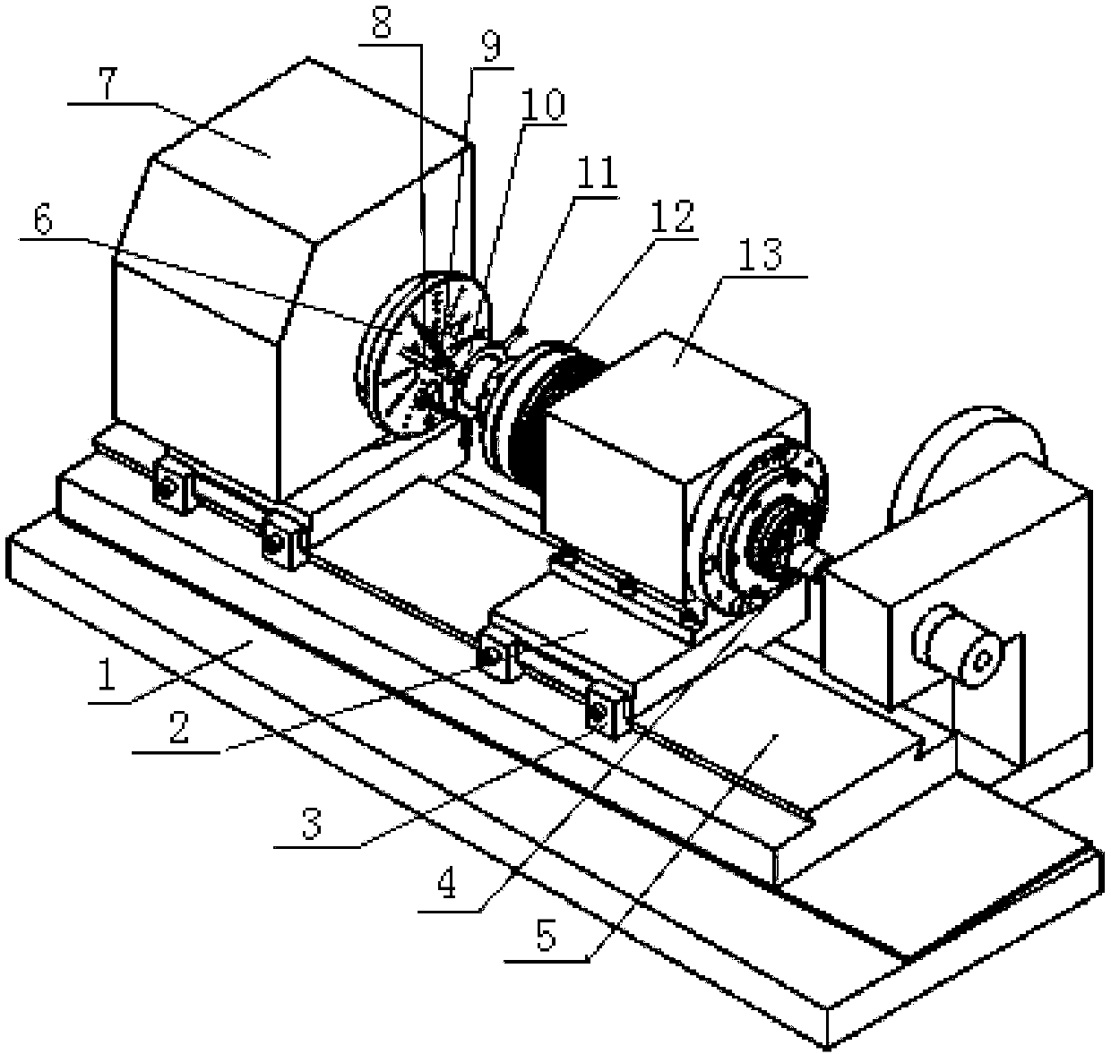
[0030] 2) According to the design requirements, the end face of the assembled spindle is provided with a finishing taper hole or a finish machining spindle end face; the center line of the taper hole ...


PUM


Abstract

The invention belongs to the field of machine assembly, and relates to an assembly method for a main shaft with a taper hole in the end face or with a precision requirement for the end face and a machining tool. The tool comprises a lathe bed, tool bases, an inner grinding head, a grinding machine guide rail, connection pieces and a grinding machine head frame. The inner grinding head is fixedly arranged on the lathe bed and can freely rotate around the axial direction of the inner grinding head. The grinding machine guide rail is arranged on the upper surface of the lathe bed and can rotate on the upper surface of the lathe bed in the horizontal direction. The tool bases are arranged on the grinding machine guide rail and can freely move in the axial direction of the grinding machine guide rail. The grinding machine head frame and the to-be-ground main shaft are arranged on the tool bases correspondingly. The grinding machine head frame is connected with the to-be-ground main shaft through the connection pieces and drives the to-be-ground main shaft to rotate around the axial direction of the grinding machine head frame. By means of the assembly method for the main shaft with thetaper hole in the end face or with the precision requirement for the end face and the machining tool, the assembly precision and quality can be effectively ensured, the assembly period can be shortened, the assembly method is convenient to achieve, and the machining tool is convenient to obtain.

Description

technical field [0001] The invention belongs to the field of mechanical assembly, and relates to a spindle assembly method, in particular to a spindle assembly method and a processing tool with a tapered hole on the end surface or a precision requirement on the end surface. Background technique [0002] see figure 1 , the shaft core with a tapered hole on the end face or the shaft core with a required end face is assembled into a main shaft, the following method is often used: the taper hole or end face of the shaft core end face is processed, and multiple sets of bearings are used to fit outside the shaft core, or use The inner spacer ring and the outer spacer ring separately install the bearing on the shaft core to block and limit the inner ring and outer ring of the bearing respectively. Finally, the gland, the shaft core and the main shaft sleeve are used to ensure that the bearing does not move and the shaft core does not move. Shifting, so as to ensure that the shaft ...

Claims


Application Information

Patent Timeline
Patent Type & Authority Applications(China)
IPC IPC(8): B24B1/00B24B5/14B24B5/48B24B7/16B23P21/00
Inventor 任强红王兴哲
Owner 陕西诺贝特自动化科技股份有限公司
Why Eureka
Try Eureka