
Surveillance system and method

a surveillance system and camera technology, applied in the field of surveillance systems and methods, can solve the problems of not having knowledge of or easy access to images generated by other people's cameras, and manual intervention to access and monitor images

Active Publication Date: 2012-12-13
CLOUDVIEW HLDG LTD INC
View PDF5 Cites 51 Cited by
  • Summary
  • Abstract
  • Description
  • Claims
  • Application Information

AI Technical Summary

Benefits of technology

[0013]In one embodiment, the management means is adapted to enable users owning or operating respective cameras to enter alert data as part of said user data to identify at least one user authorised to access image data from said cameras to receive said alerts for images received for said respective cameras; and said alert means is adapted to generate said alert in dependence upon said alert data in said information storage means. This enables users to set up their desired alert types, the alert messages and even the user to whom the alert is to be sent since it is not necessary for the alerts to be sent to the user that owns or controls the camera. It is possible for the alert to be sent to multiple users in a community.
[0021]The map functionality provides a graphical user interface for users to manage their user accounts, cameras, and communities in a simple and intuitive manner and to gain knowledge of and easy access to images for cameras owned by other users.

Problems solved by technology

Closed Circuit Television (CCTV) has been available for many years but suffers from the requirement for it to be manually monitored if the images are to be used real time, otherwise it simply acts as a recordal system.
Although such systems benefit from accessibility anywhere in the world, they require manual intervention to access and monitor the images generated.
Further, people are generally required to monitor their own cameras and do not have knowledge of or easy access to images from other people's cameras.

Method used


Image

  • Surveillance system and method
  • Surveillance system and method
  • Surveillance system and method

Examples


Embodiment Construction

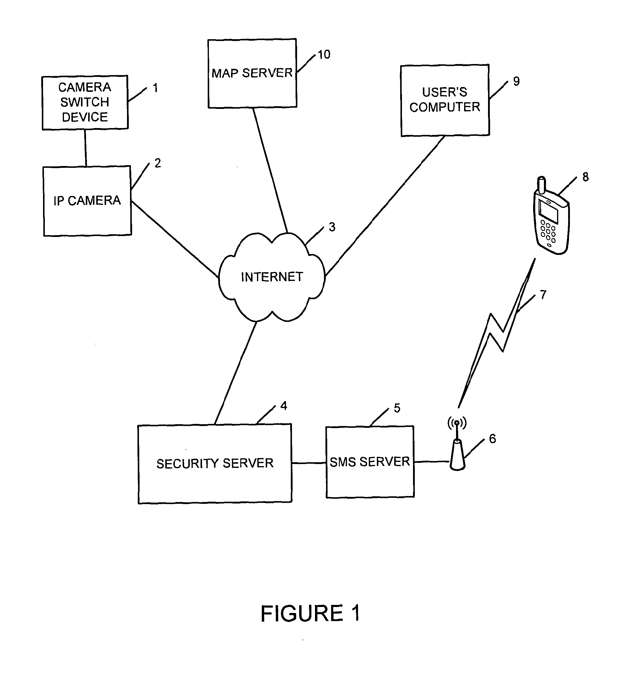
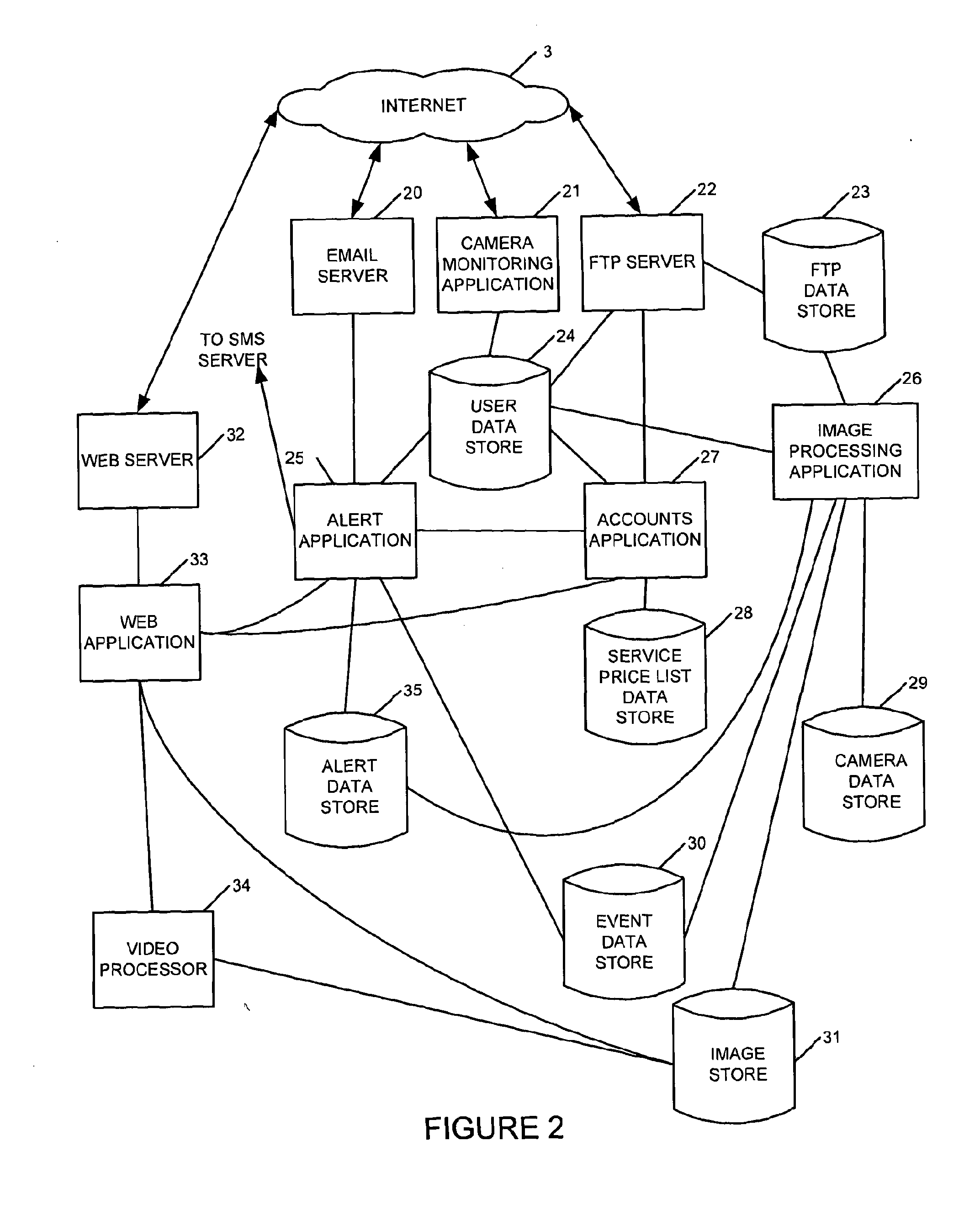
[0030]An embodiment of the present invention will now be described with reference to FIGS. 1 to 7.

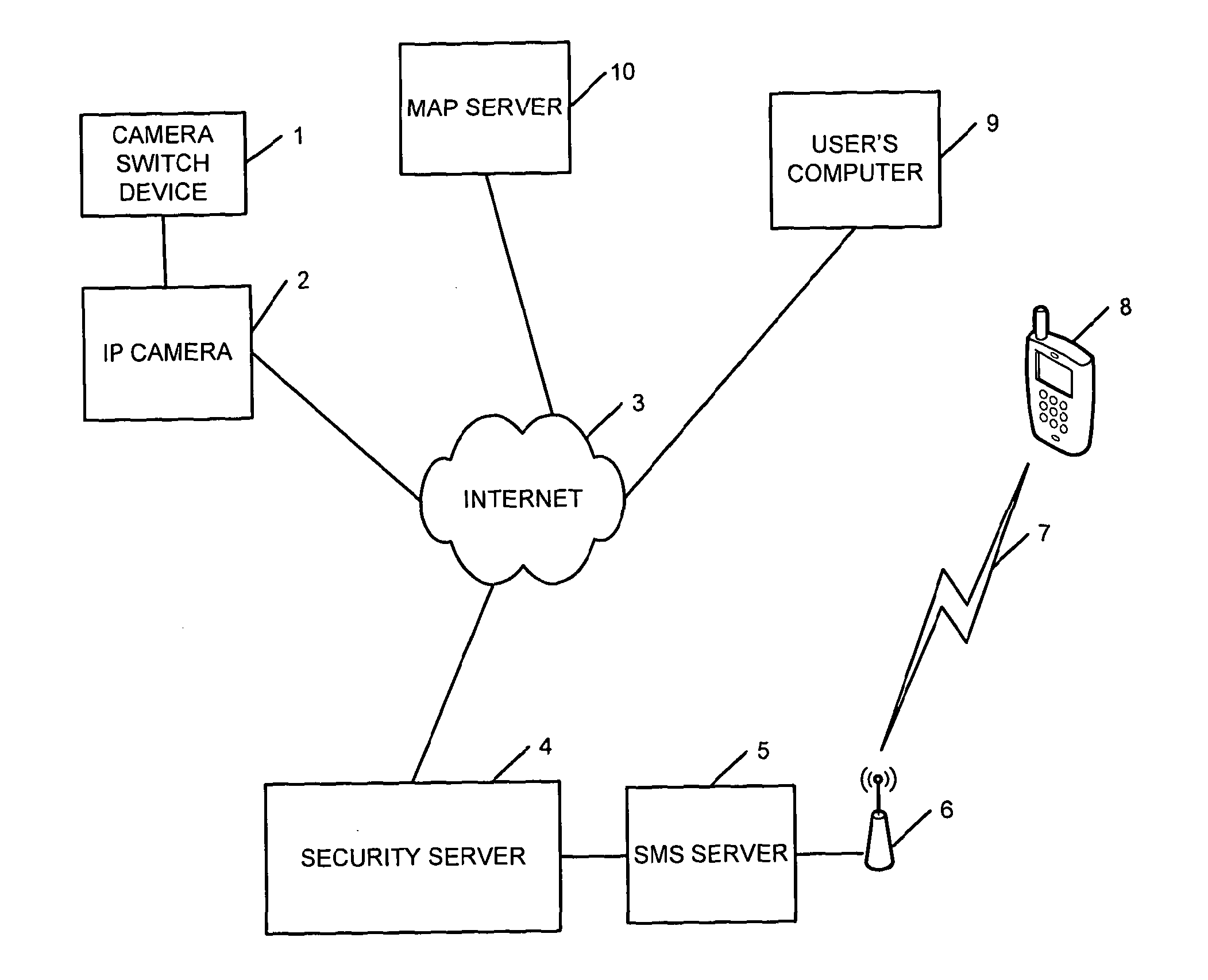
[0031]FIG. 1 illustrates a surveillance system providing a surveillance service. An internet protocol (IP) camera 2 is provided connected to the internet 3. Although only one IP camera 2 is shown in FIG. 1, in practice there will be many cameras connected and operated by many different users: some users operating more than one camera. The IP camera 2 operates to capture images based on a trigger event. Such cameras are known in the art and provide for the capture of an image ready for remote accessing over the internet or upload to a remote server. Thus the IP camera 2 includes memory for the storage of images captured as a result of trigger events.

[0032]The IP camera 2 is provided at a location at which surveillance is required. A number of such IP cameras 2 can be provided in a building or in an area to provide for complete surveillance. Such IP cameras 2 can be owned by a single enti...


PUM


Abstract

A surveillance method and system is provided for receiving image data from a plurality of said cameras; storing the received image data identifying each camera from which the image data originated; enabling each of a plurality of camera users who own or operate respective cameras to assign a said camera owned or operated by the camera user to at least one said set of cameras and to authorise selected users of the system to access image data from said at least one set of cameras, wherein said users of the system can include camera users and / or users not owning or operating any cameras; storing camera set data identifying the assigned camera as belonging to said set of cameras; storing user data identifying the users authorised to access image data from said set of cameras; and outputting image data to users dependent upon said camera set data and said user data.

Description

FIELD OF THE INVENTION[0001]The present invention generally relates to a surveillance system and method for use on a network such as the internet.BACKGROUND OF THE INVENTION[0002]Surveillance cameras have become ever more prevalent in society for people looking for enhanced security. Closed Circuit Television (CCTV) has been available for many years but suffers from the requirement for it to be manually monitored if the images are to be used real time, otherwise it simply acts as a recordal system.[0003]With the advent of the internet and Internet protocol (IP) enabled cameras it has become possible for people to control and access images from cameras acting as Surveillance cameras over the Internet. Although such systems benefit from accessibility anywhere in the world, they require manual intervention to access and monitor the images generated. Further, people are generally required to monitor their own cameras and do not have knowledge of or easy access to images from other peopl...

Claims


Application Information

Patent Timeline
IPC IPC(8): G08B21/00H04N5/225
CPCG08B13/19656G08B25/004H04N7/188H04N7/185H04N7/181
Inventor BARKER, SIMON PETER DUDLEYBECHER-WICKES, JAMESHAMILTON, KEITH ALISTAIRSEARLES, ROBERT LAURENCESEARLES, ROBERT VIVIANWOOD, ELIZABETH CLARE
Owner CLOUDVIEW HLDG LTD INC
Learn More