Fire monitoring system and method using composite camera

a composite camera and monitoring system technology, applied in the field of fire monitoring systems and methods using composite cameras, can solve the problems of adding huge costs to build a fire monitoring system, inconvenient administrators standing by to monitor videos, etc., and achieve the effect of easy detection of a fire and easy identification

Inactive Publication Date: 2012-12-13
CHANG SUNG CO LTD
View PDF8 Cites 74 Cited by
  • Summary
  • Abstract
  • Description
  • Claims
  • Application Information

AI Technical Summary

Benefits of technology

[0007]Accordingly, the present invention has been devised to solve the above-mentioned problems, and an object of the present invention is to provide a fire monitoring system and method using composite camera, which can measure a separation distance between the infrared camera and a point of fire by using per-pixel detecting area data which is calculated by using resolution and field of view of the infrared camera and is pre-stored in memory unit, and thus which can detect the point of fire by using only an infrared camera and without using an expensive distance measuring device.
[0008]And, another object of the present invention is to provide a fire monitoring system and method using composite camera, which can detect a point with a temperature value exceeding the maximum value of pre-set fire hazard temperature range from an infrared video as a point of fire, analyze a set of coordinate values of the point of fire and analyze a point of fire on a visible light video which captures the same region where the infrared video captures by using the set of coordinate values, and thus which can provide a clear vision of the point of fire with the visible light video.
[0009]And, still another object of the present invention is to provide a fire monitoring system and method using composite camera, which can mark a pre-set shape or a pre-set color at a point of fire on a visible light video thus enabling easy detection of a fire with an easily identifiable mark on the point of fire, and which can provide information such as a temperature value of the point of fire, a timestamp corresponding to the time when the point of fire is detected, speed and direction of wind and a distance between the point of fire and the composite camera thus helping administrators plan for suppressing a fire in a shortest possible time with consideration of an elapsed time since the fire, time needed to get to the point of fire, ways to block passage of the fire and ways to suppress the fire and such.
[0020]And, the controlling unit may be further characterized by: saving a visible light video and an infrared video captured by the composite camera into the memory unit during a pre-set time interval while outputting the visible light video and the infrared video to an administrator terminal, and deleting a previously saved video after the pre-set time interval; and saving the visible light video and the infrared video into the memory unit continuously after a fire is detected if fire alert level is in alert stage.
[0031]And, the controlling unit may be further characterized by: saving a visible light video and an infrared video captured by the composite camera into the memory unit during a pre-set time interval while outputting the visible light video and the infrared video to an administrator terminal, and deleting a previously saved video after the pre-set time interval; and saving the visible light video and the infrared video into the memory unit continuously after a fire is detected if fire alert level is in alert stage.

Problems solved by technology

Conventional fire monitoring systems and methods use multiple surveillance cameras to capture fire hazard areas, and then administrators detect a fire from videos captured by the surveillance cameras by watching them via administrator terminals and give an alarm manually if a fire is detected, thus accompanying inconvenience that there should be administrators standing by to monitor the videos.
And, since it is impossible to find out the exact point of fire with only videos captured by surveillance cameras, conventional fire monitoring systems and methods has needed a separate fire positioning device such as LRF (Laser Range Finder).
LRF is a widely used distance measuring device using laser, but is very expensive, thus adding huge costs to build a fire monitoring system.

Method used


Image

  • Fire monitoring system and method using composite camera
  • Fire monitoring system and method using composite camera
  • Fire monitoring system and method using composite camera

Examples


Embodiment Construction

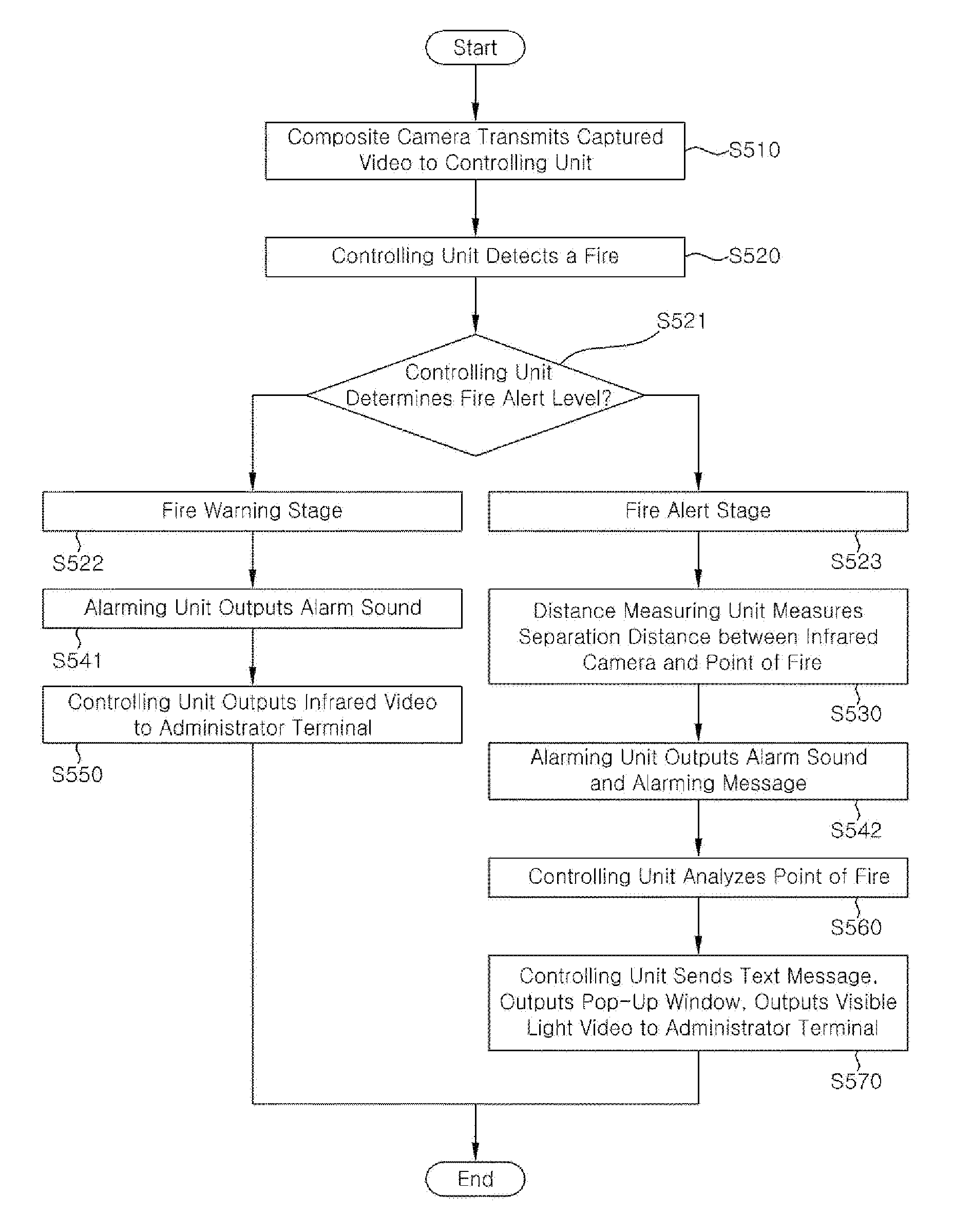
[0037]Embodiments of the present invention will be described in detail with reference to the accompanying drawings.

[0038]Merits and characteristics of the present invention and methods for achieving them will become apparent from the following embodiments taken in conjunction with the accompanying drawings. However, the present invention is not limited to the disclosed embodiments, but may be implemented in various ways. The embodiments are provided to complete the disclosure of the present invention and to allow those having ordinary skill in the art to fully understand the scope of the present invention. The present invention is defined only by the scope of the claims.

[0039]The same reference numerals will be used throughout the drawings to refer to the same or like elements.

[0040]Hereinafter, embodiments of the present invention will be described with reference to the drawings which illustrate a fire monitoring system using composite camera.

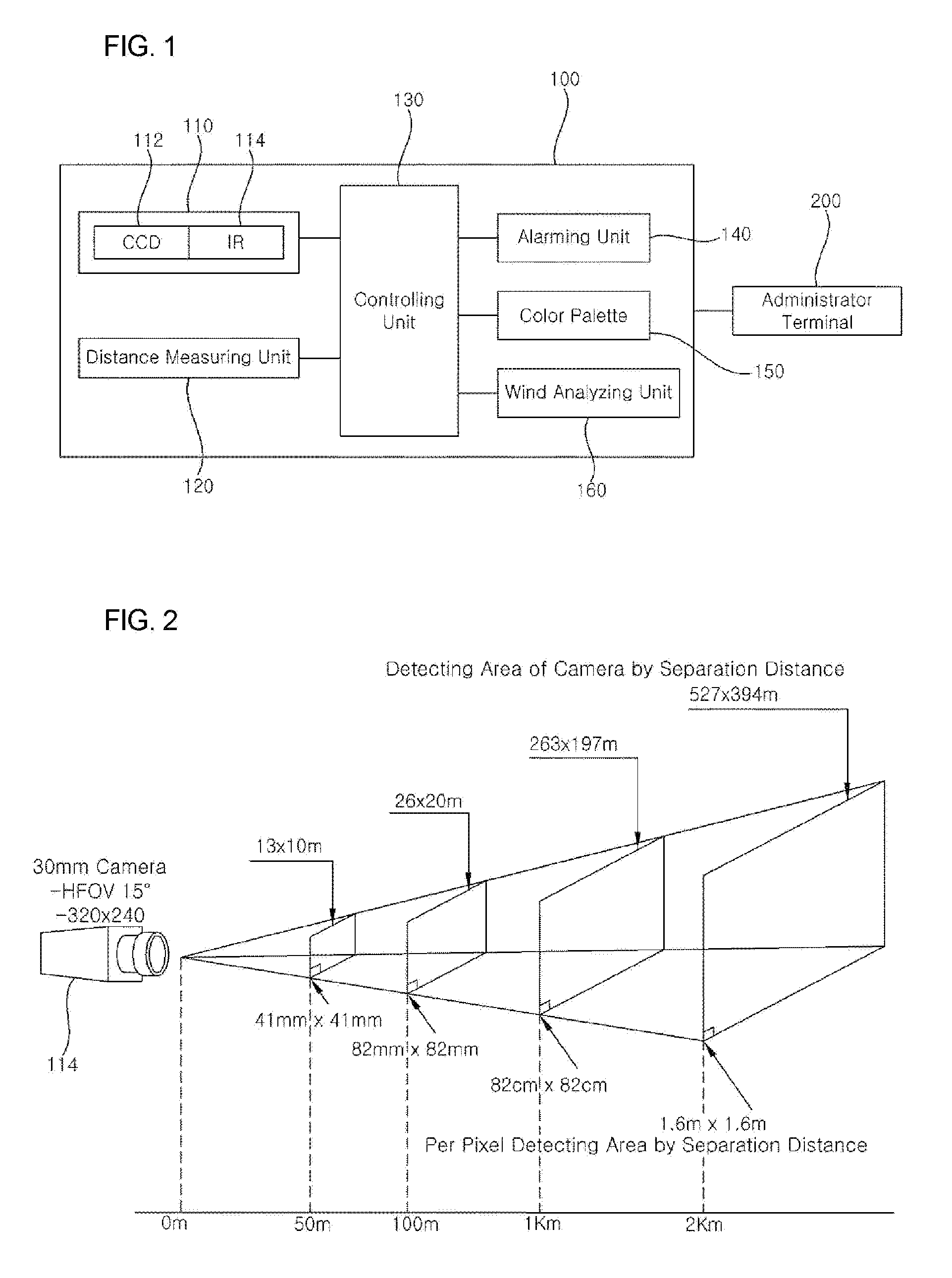
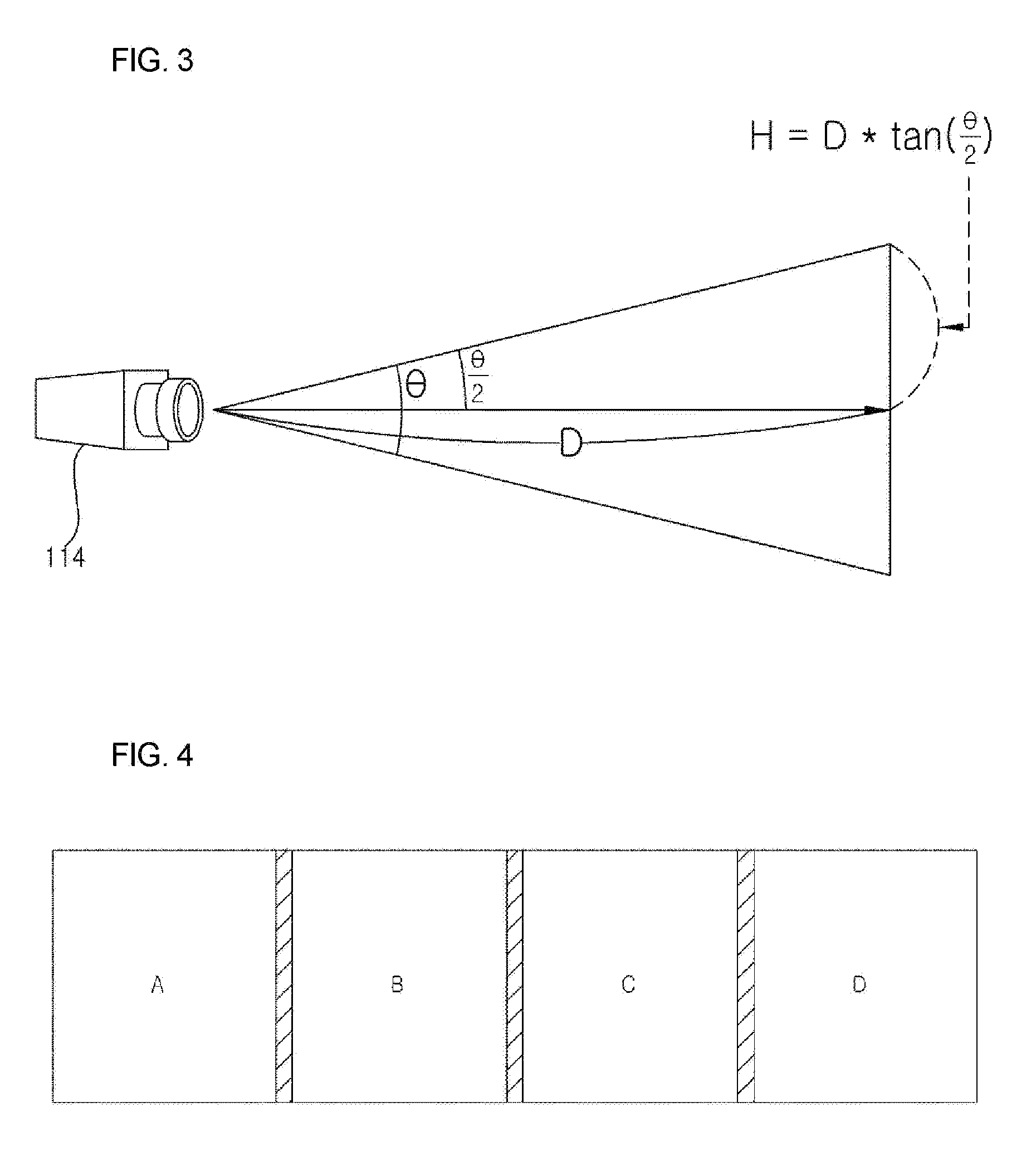
[0041]FIG. 1 is a block diagram showing...


PUM


Abstract

Provided is a fire monitoring system and method using composite camera, which can measure a separation distance between the infrared camera and a point of fire by using per-pixel detecting area data which is calculated by using resolution and field of view of the infrared camera and is pre-stored in memory unit, and thus which can detect the point of fire by using only an infrared camera and without using an expensive distance measuring device.

Description

CROSS REFERENCE[0001]This application claims foreign priority under Paris Convention and 35 U.S.C. §119 to Korean Patent Application No. 10-2011-0055918, filed Jun. 10, 2011 with the Korean Intellectual Property Office.BACKGROUND OF THE INVENTION[0002]1. Field of the Invention[0003]The present invention relates to a fire monitoring system and method using composite camera, and more particularly, to a fire monitoring system and method using composite camera, which can analyze a point of fire using an infrared camera and outputs a variety of information to an administrator terminal, thus helping administrators plan for suppressing a fire in a shortest possible time with consideration of an elapsed time since the fire, time needed to get to the point of fire, ways to block passage of the fire and ways to suppress the fire and such.[0004]2. Description of the Related Art[0005]The present invention relates to a fire monitoring system and method using composite camera. Conventional fire m...

Claims


Application Information

Patent Timeline
Patent Type & Authority Applications(United States)
IPC IPC(8): G08B17/12H04N5/33H04N7/18
CPCG08B17/12G08B17/125
Inventor LEE, YEU YONGSONG, MYUNG WOON
Owner CHANG SUNG CO LTD
Why Eureka
Try Eureka