Meter unit

a technology of meter unit and meter body, which is applied in the direction of instruments, mechanical equipment, gearing, etc., can solve the problems of unsuitable above-described structure, and achieve the effect of not deteriorating light guide performance and easy arrangemen

Active Publication Date: 2012-12-20
YAZAKI CORP
View PDF49 Cites 8 Cited by
  • Summary
  • Abstract
  • Description
  • Claims
  • Application Information

AI Technical Summary

Benefits of technology

[0028]According to the meter unit having the above structure, a stable load spring can be obtained, a smooth rotating operation of the rotation shaft can be obtained and a light guide performance is not deteriorated.
[0029]According to the meter unit having the above structure, since the spring abutting member constantly comes into contact with at least a part of the annular braking spring, even when the braking spring rotates integrally with the gear that accommodates the braking spring or the rotation shaft, the spring contacting member can be constantly pressed so as to allow the braking spring to generate a load to the gear. As a result, the rotating operation of the rotation sha

Problems solved by technology

Accordingly, the above-described structure is

Method used


Image

  • Meter unit
  • Meter unit
  • Meter unit

Examples


first embodiment

[0092]Now, an operation of the first embodiment will be described below.

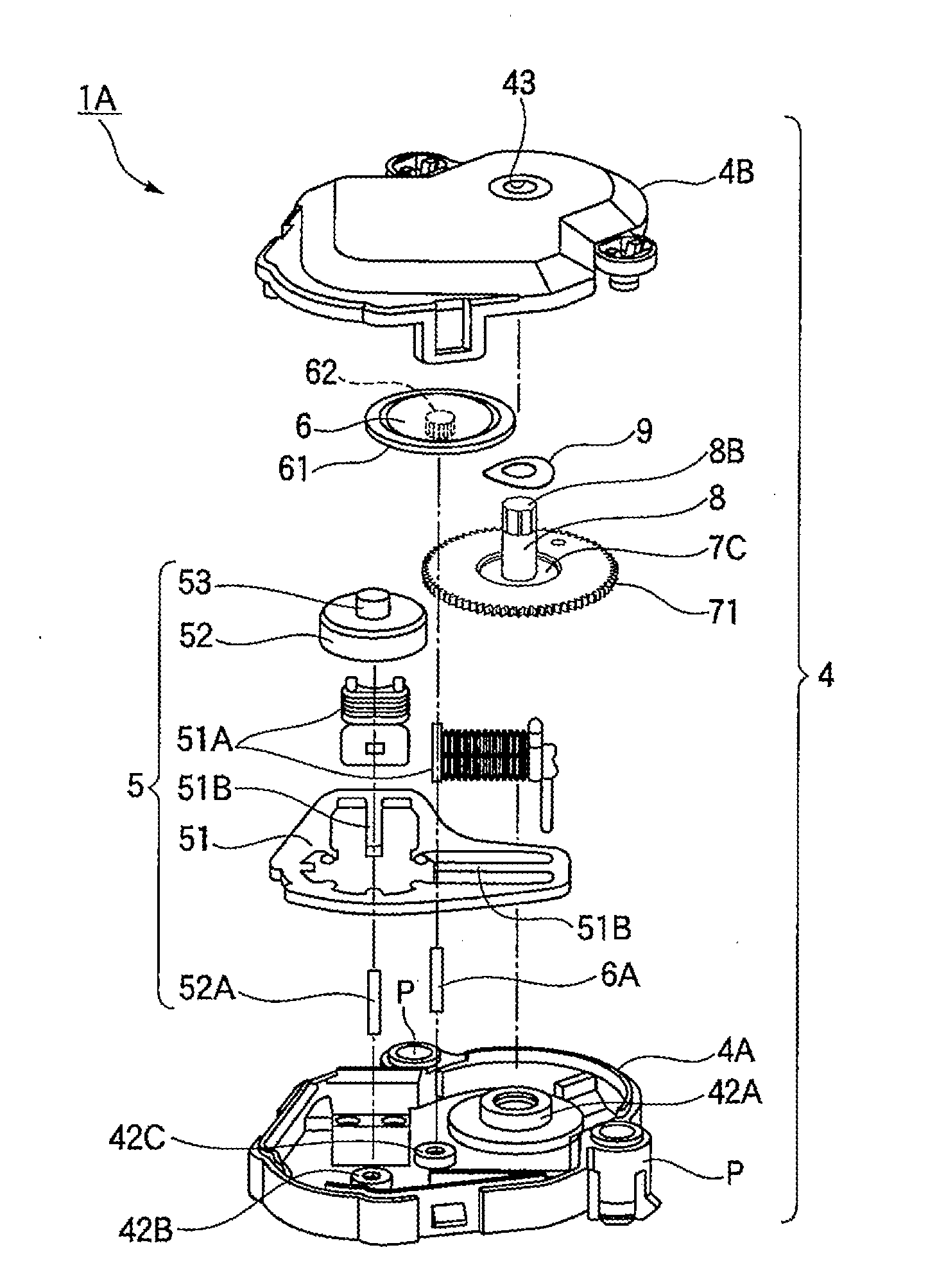
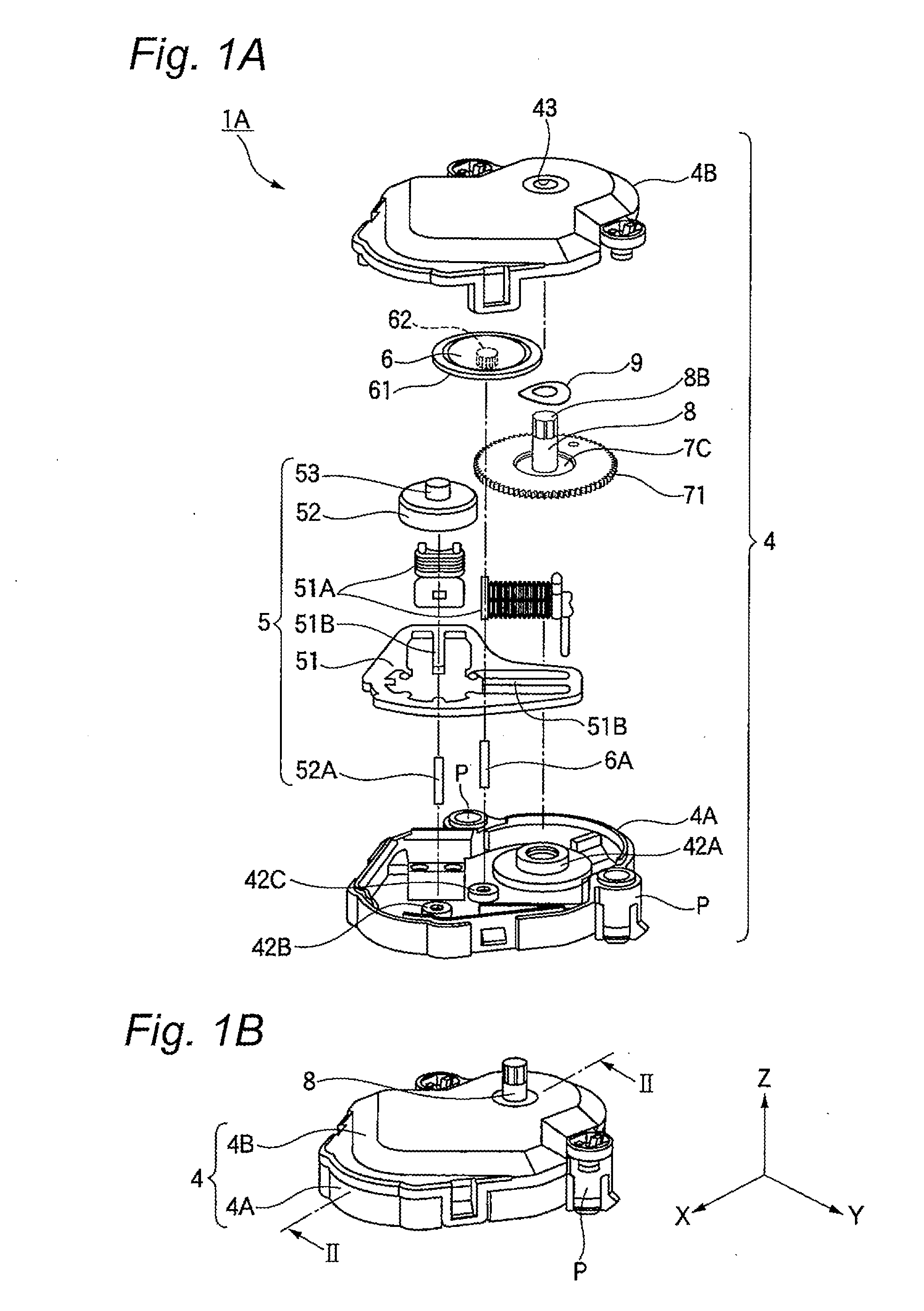
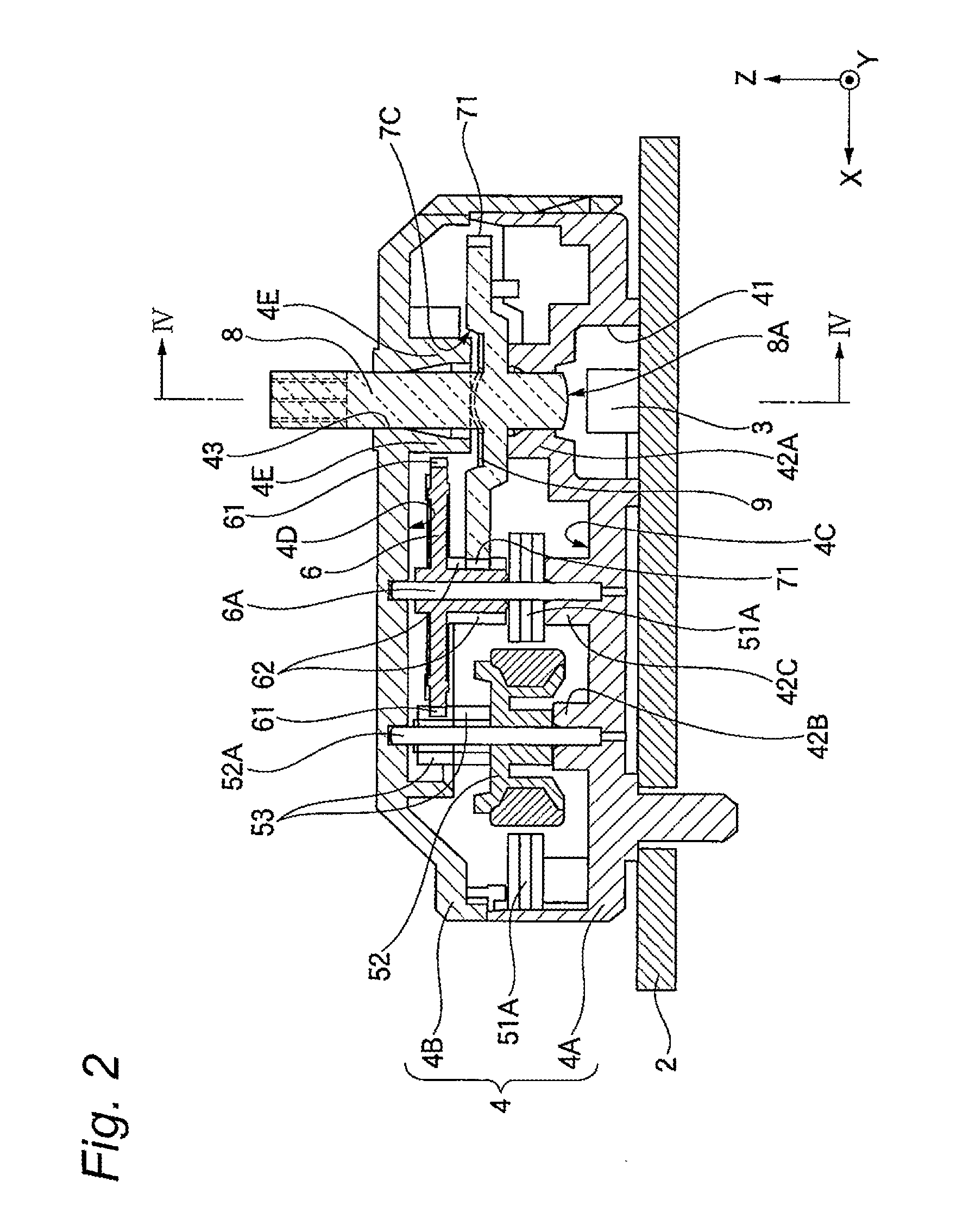
[0093]For instance, even when a minute swing movement or vibration arises in the step motor 5, or a backlash arises in the bearing part of the rotation shaft 8, the braking spring 9 having a stable spring load can effectively absorb the vibration. Accordingly, the minute swing movement or vibration of the rotation shaft 8 can be prevented.

[0094]Further, for instance, when any impact is applied to a vehicle body side during a driving to transmit the impact to the lower case 4A (similarly to the upper case 4B) of the motor case 4 through the base board 2, an impact force thereof is propagated to the output gear 7 and the braking spring 9 accommodated in the recessed portion 7C of the output gear 7 from the bearing 42A forming the lower bearing of an inner face (the floor face) side of the lower case 4A. Then, the braking spring 9 is resiliently deformed to absorb and damp the impact force. Further, the output gear...

second embodiment

[0113]On the other hand, in the meter unit 1B of the second embodiment having the stopper member 4G, when the rotation shaft 8 formed integrally with the output gear 7 is moved to the highest position of the clearance γ, as shown in FIGS. 11A and 11B, the upper face 7A of the output gear 7 on which an area of the recessed portion 7C is excluded butts against the end face 4H of the stopper member 4G. In this case, the clearance γ is smaller than the clearance γ′. Thus, the rotation shaft 8 is prevented from being lifted more.

[0114]Thus, even when a pressing force is applied to the braking spring 9 to bring the braking spring to a state near a flat state as shown in FIGS. 11A and 11B, the braking spring 9 is not pressed until the braking spring 9 is brought to a completely flat state as shown in FIGS. 12A and 12B. Accordingly, the plastic deformation of the braking spring 9 can be avoided.

[0115]The present invention is not limited to the above-described embodiments, and various kinds ...


PUM


Abstract

A meter unit includes a step motor, a gear, a braking spring and a case. The gear has a gear body a rotation shaft. The braking spring urges the gear in a direction of an axis of rotation of the gear. The case accommodates the step motor, the gear body, a part of the rotation shaft, and the braking spring therein. The braking spring has a shape through which the first part of the rotation shaft passes. A first face of the gear body is formed with a recessed portion which accommodates the braking spring. A first part of the case supports a second face of the gear body. A second part of the case is configured to press the braking spring so that entire part of the braking spring is accommodated in the recessed portion.

Description

CROSS REFERENCE TO RELATED APPLICATION[0001]This application is a continuation of PCT application No. PCT / JP2011 / 059332, which was filed on Apr. 8, 2011 based on Japanese Patent Application (No. 2010-090696) filed on Apr. 9, 2010, the contents of which are incorporated herein by reference. Also, all the references cited herein are incorporated as a whole.BACKGROUND OF THE INVENTION[0002]1. Technical Field[0003]The present invention relates to a meter unit used in a meter device that rotatably supports a rotation shaft which a pointer is attached, in the meter devices of various uses for a meter for a motor vehicle, a meter for a ship, a meter for an aircraft or the like.[0004]2. Background Art[0005]In meter devices used in various kinds of meters, a motor and a gear for transmitting torque from the motor to a rotation shaft are accommodated in a case, and the rotation shaft to which the turning force or torque from the gear is transmitted to rotate is rotatably supported relative to...

Claims


Application Information

Patent Timeline
IPC IPC(8): F16H19/08
CPCG01D11/10Y10T74/18568H02K7/116G01D11/28H02K5/16H02K7/102
Inventor FUKUDA, TAISEI
Owner YAZAKI CORP
Why Eureka
Try Eureka