Solid state light fixture with a tunable angular distribution

a solid-state light fixture and angular distribution technology, which is applied in the direction of lighting applications, light source combinations, instruments, etc., can solve the problems of inconvenient adjustment, prone to failure, and generally inability to easily adjust the fixture to produce a narrow beam

Active Publication Date: 2012-12-20
FLUENCE BIOENG INC
View PDF7 Cites 95 Cited by
  • Summary
  • Abstract
  • Description
  • Claims
  • Application Information

AI Technical Summary

Benefits of technology

[0007]Another embodiment is a light fixture. The light fixture includes a plurality of selectively electrically controllable light emitting diodes (LEDs). The plurality of LEDs emit light in essentially the same direction with essentially the same spectral profile. The light fixture also includes a plurality of lenses corresponding to at least some of the plurality of LEDs. Each lens that receives emitted light from a corresponding LED produces a transmitted beam having one of a predetermined number of angular beam widths. Each LED that does not h...

Problems solved by technology

For instance, if a particular fixed-width light fixture is designated as having a “wide” beam, the fixture generally cannot be adjusted easily to produce a “narrow” beam.
First, they may be prone to failure because they include moving p...

Method used


Image

  • Solid state light fixture with a tunable angular distribution
  • Solid state light fixture with a tunable angular distribution
  • Solid state light fixture with a tunable angular distribution

Examples


Embodiment Construction

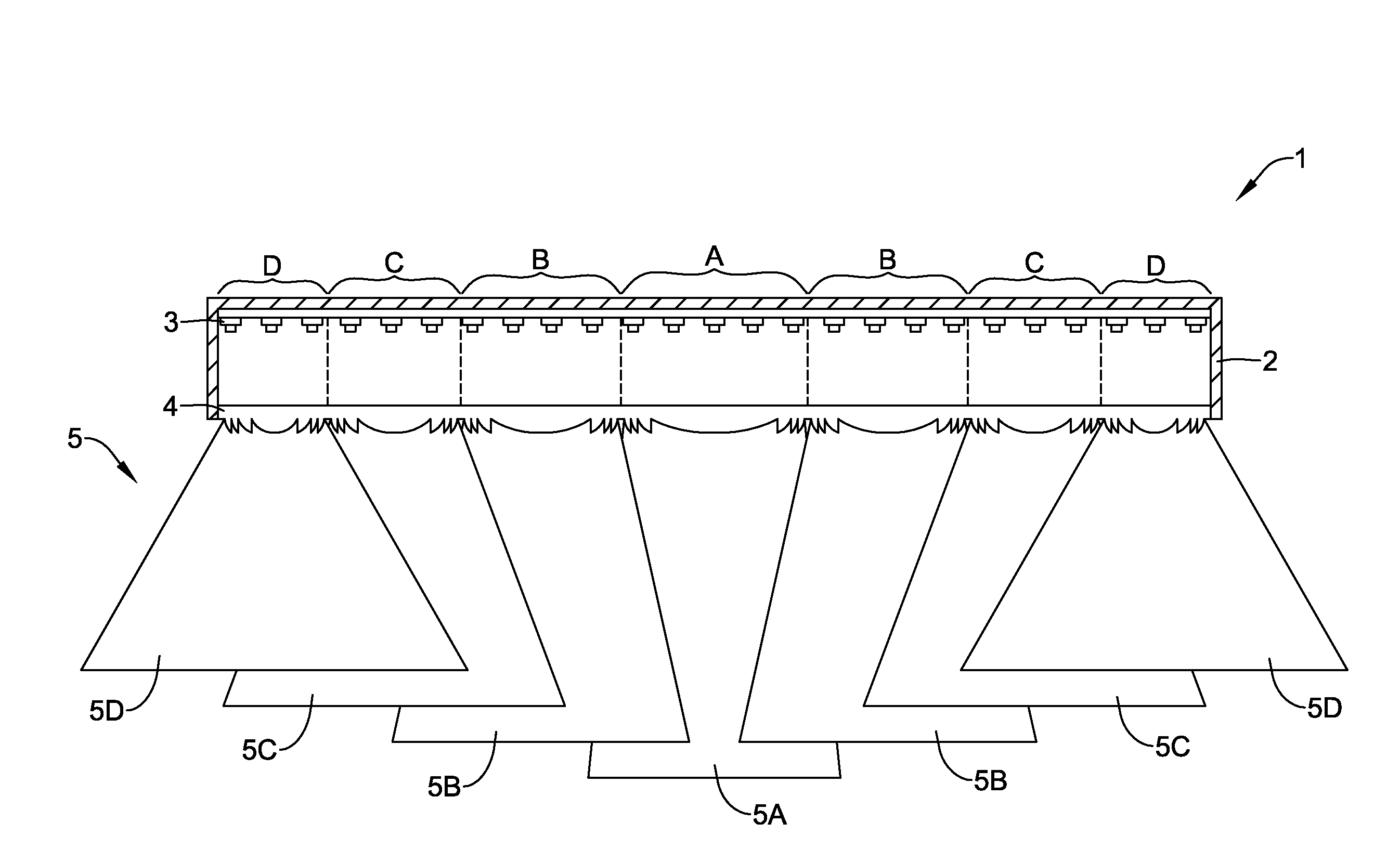
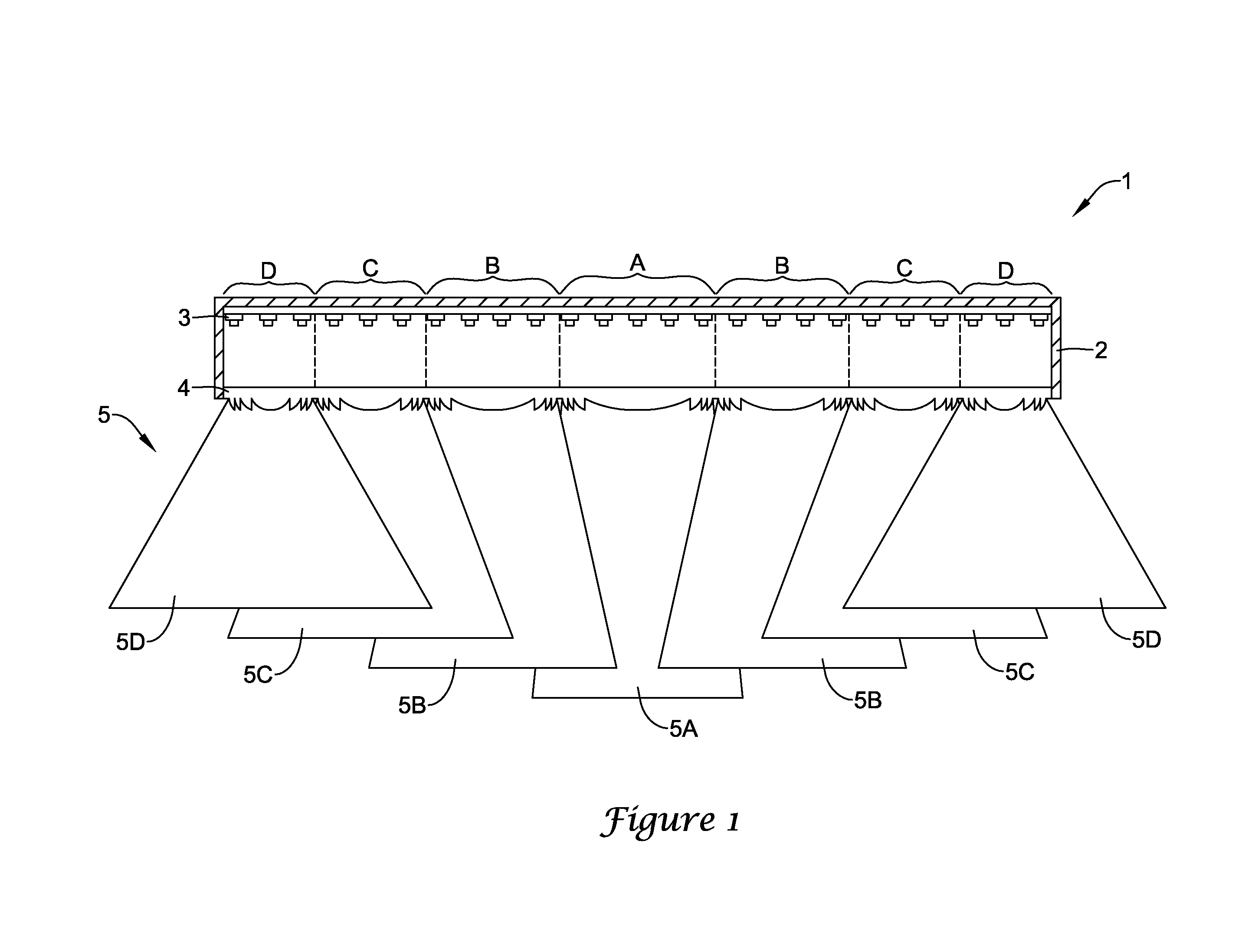
[0018]In this document, the directional terms “up”, “down”, “top”, “bottom”, “side”, “lateral”, “longitudinal” and the like are used to describe the absolute and relative orientations of particular elements. For these descriptions, it is assumed that the light fixture is mounted overhead, such as being incorporated into a ceiling tile or ceiling grid, and that the light fixture directs its output generally downward toward a user. It will be understood that while such descriptions provide orientations that occur in typical use, other orientations are certainly possible. For instance, the fixture may be wall-mounted or incorporated into additional elements to provide indirect lighting. The noted descriptive terms, as used herein, still apply to the fixture, even if the fixture has an orientation other than overhead, or is uninstalled in its overhead orientation.

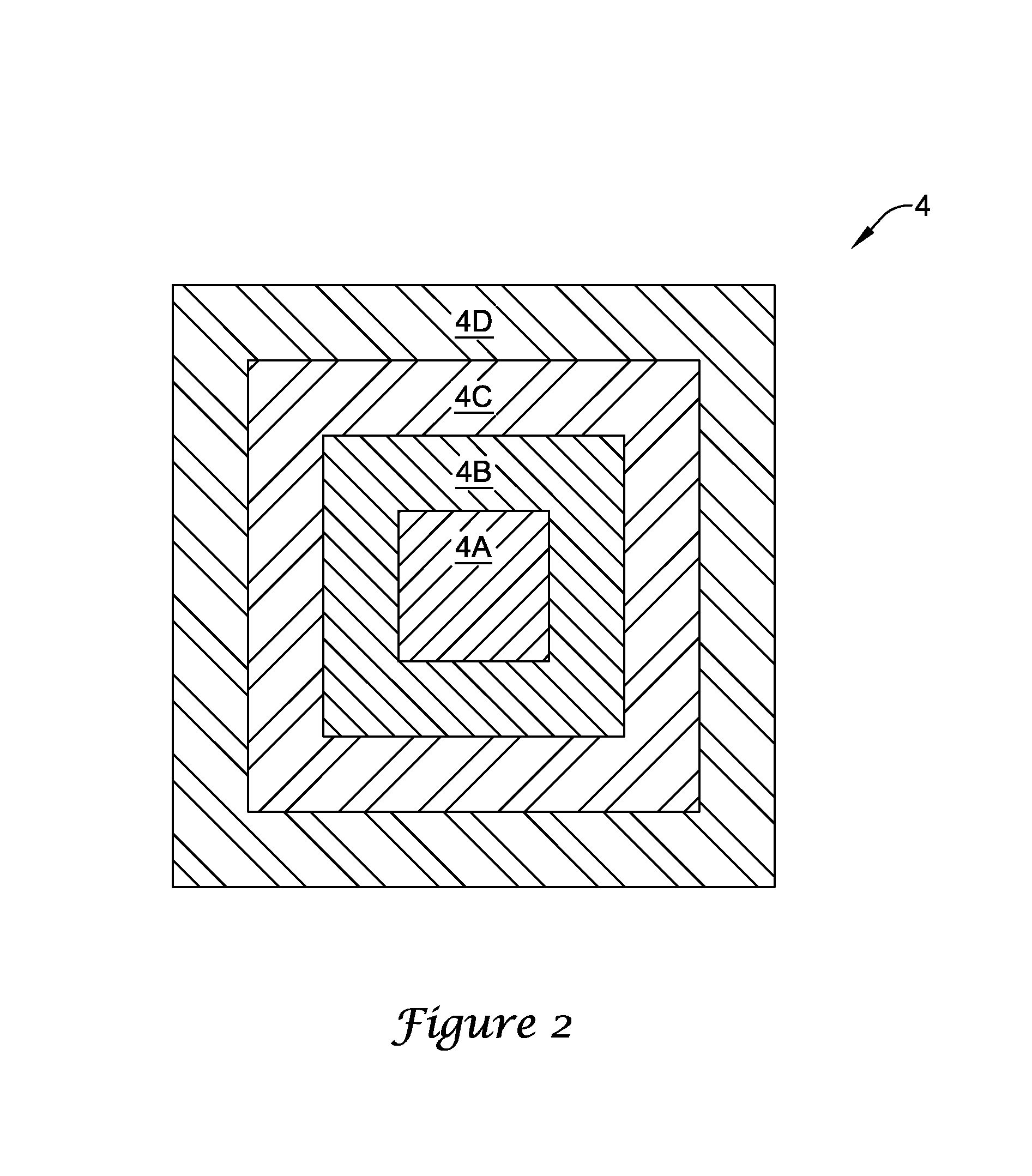
[0019]A light fixture having a controllable angular distribution is disclosed. The fixture may include a lens with a lateral ...


PUM


Abstract

A light fixture may include LEDs that each emits light into a particular zone on a lens, where each zone has its own focal properties. Each LED may be grouped into one (or more) subset(s) that corresponds to the zone(s) struck by its emitted light. The LEDs may be selectively electrically controllable, so that the amount of light transmitted through each zone may be controllable by the electrical control system of the fixture. Because light transmitted through different zones emerges from the fixture having different widths, the electrical control system can directly control the amount of light emerging at each width. By mixing relatively narrow light with relatively wide light in the proper proportions, the electrical control system of the fixture may produce light having any desired angular profile between “narrow” and “wide”. One may think of the fixture having a controller that features both a dimmer, which can control the optical power or brightness of the fixture 1, and a “width” controller, which can dial in values between “narrow” and “wide” light. By varying the relative contributions of the different beam widths, the angular profile of the total output may be varied, and may advantageously be varied electronically, without any moving parts.

Description

TECHNICAL FIELD[0001]The present invention relates to a light fixture having an adjustable angular distribution, and a method of varying said angular distribution.BACKGROUND OF THE INVENTION[0002]Many light sources for general illumination, such as linear fluorescent fixtures and some parabolic aluminized reflector lamps, typically have a fixed angular distribution of light that is a property of the light source. For instance, if a particular fixed-width light fixture is designated as having a “wide” beam, the fixture generally cannot be adjusted easily to produce a “narrow” beam.[0003]An improvement to the fixed-width fixture is an adjustable-width fixture. Typically, these fixtures rely on mechanical movement to produce a change in the width or distribution of the output beam. For instance, moving a source relative to a reflector or a lens may produce a change in the output beam width. As another example, an adjustable aperture or iris may be used to block light that falls outside...

Claims


Application Information

Patent Timeline
IPC IPC(8): H05B37/02F21V5/00
CPCF21S8/04F21V5/002F21V5/007F21V5/008F21V5/045F21W2131/205F21W2131/406F21Y2101/02F21Y2105/001F21Y2113/005F21V23/04F21Y2105/10F21Y2115/10F21Y2113/13
Inventor QUILICI, MICHAELOLSEN, JOSEPH ALLEN
Owner FLUENCE BIOENG INC
Why Eureka
Try Eureka