Electrical control unit

Active Publication Date: 2012-12-20
HITACHI ASTEMO LTD
View PDF4 Cites 55 Cited by
  • Summary
  • Abstract
  • Description
  • Claims
  • Application Information

AI Technical Summary

Benefits of technology

[0006]However, due to an inherent construction of the endless groove formed in the case, a not-small distance is needed between the endless groove and the printed wiring board, which suppresses the case and thus the entire construction of the electrical control unit from having a sufficiently compact size.
[0007]Accordingly, it is an object of the present invention to provide an electrical control unit which is compact in size while assuring a sealing between a case and a cover.
[0008]In accordance with a first aspect of the present invention, there is provided an electrical control unit which comprises a first member (12) having a sealing groove (30) on a first contact surface thereof; a second member (13) having a protrusion (25) on a second contact surface thereof, the protrusion being put in the groove of the first member when the second member (13) is properly put on the first member (12) to define therebetween a board receiving space; a printed wiring board (11) received in the board receiving space, the printed wiring board having an electronic part (14) mounted thereon; and a sealing material (20) received in the groove (30), the sealing material being pushed away from the groove to a space between the first and second contact surfaces for bonding the first and second contact surfaces when the protrusion is inserted into the groove while pressing the sealing material, wherein the groove comprises inner and outer side walls (31, 32) that are connected through a rounded bottom wall, a height of the inner side wall being smaller than that of the outer side wall, and wherein a peripheral edge portion of the printed wiring board is put on a top of the inner side wall in a manner to serve as an extra part of the inner side wall.
[0009]In accordance with a second aspect of the present invention, there is provided an electrical control unit which comprises a first member (12) having a first contact surface on which a groove (30) is provided; a second member (13) having a second contact surface on which a protrusion (25) is provided, the protrusion being put in the groove of the first member when the second member is coupled with the first member to define therebetween a board receiving space; a printed wiring board (11) received in the board receiving space, the printed wiring board having an electronic part (14) mounted th

Problems solved by technology

However, due to an inherent construction of the endless groove formed in the case, a not-small distance is needed between the endless groove and the p

Method used


Image

  • Electrical control unit
  • Electrical control unit
  • Electrical control unit

Examples


first embodiment

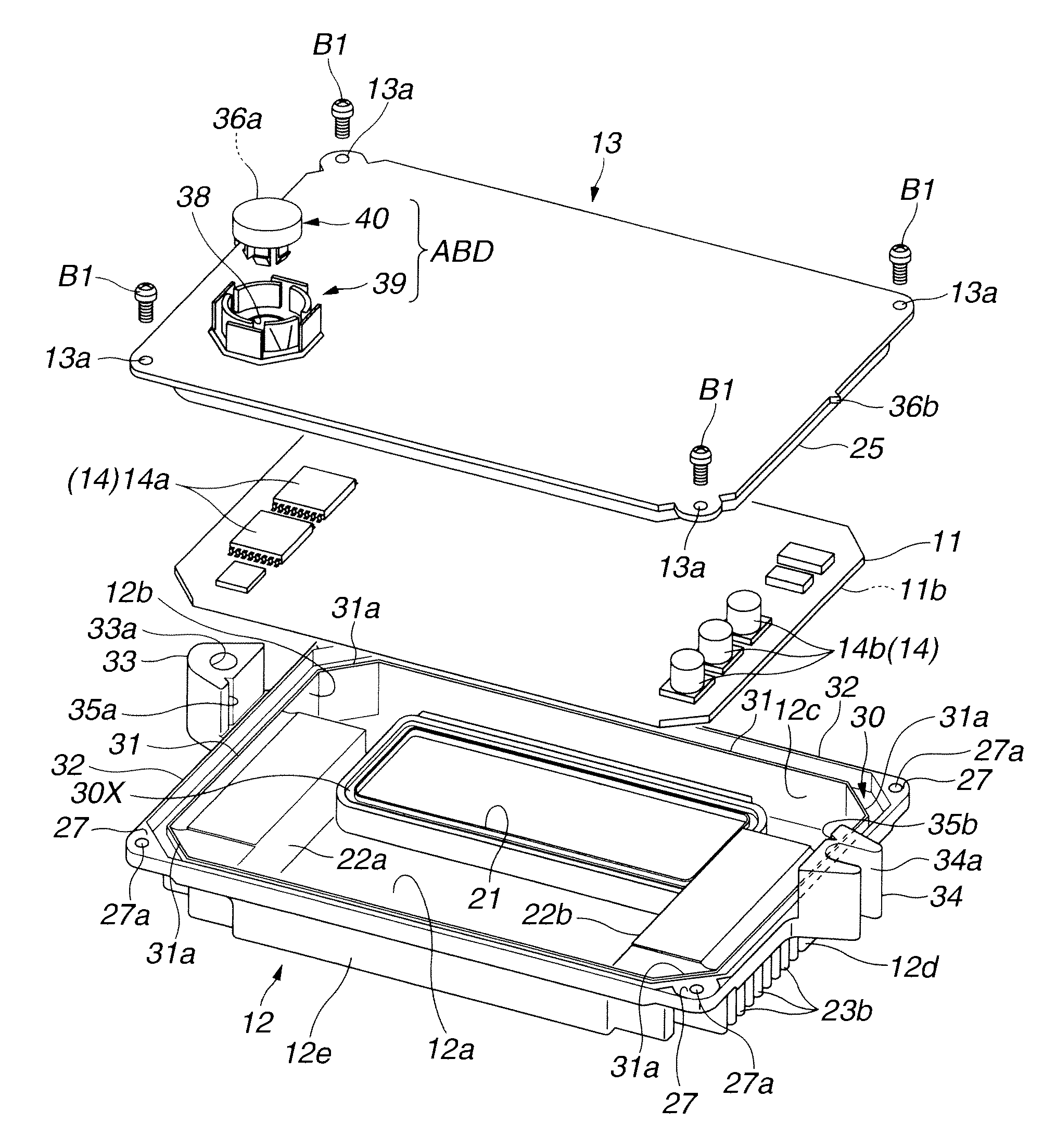
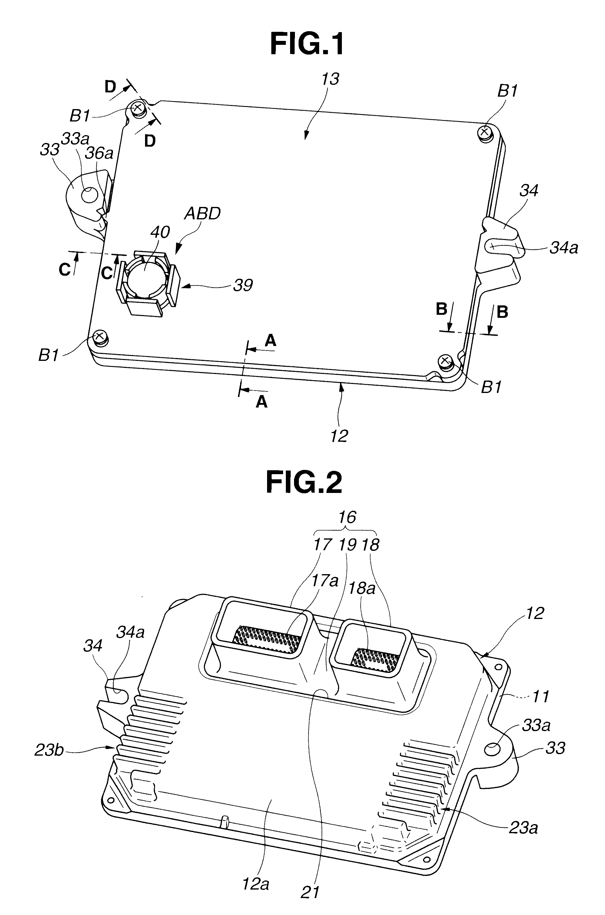
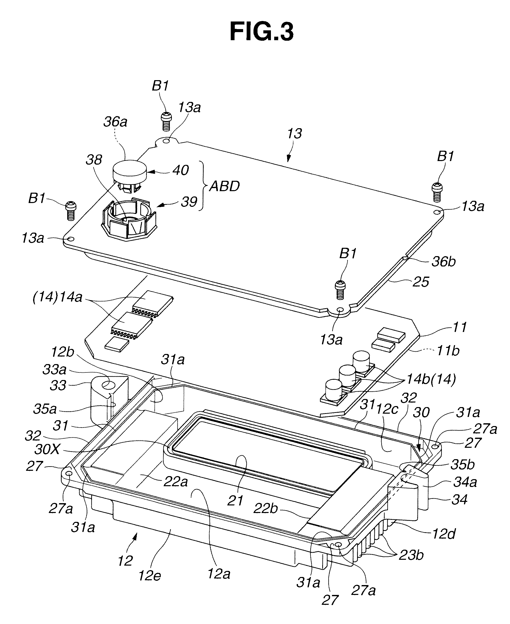
[0031]Referring to FIGS. 1 to 8, there is shown an electrical control unit of the present invention.

[0032]As is well understood from FIG. 3, the electrical control unit generally comprises a printed wiring board 11 that is equipped at its upper and lower surfaces with various electronic parts 14 such as condensers, coils, transistors, ICs (viz., integrated circuits) and the like, a case 12 that has a recess slightly larger than printed wiring board 11 and tightly installs therein printed wiring board 11 and a cover 13 that is connected to a mouth portion of case 12 to cover the recess of case 12 through a plurality of connecting screws B1. Although not shown, electrical control unit is mounted in an engine room of a motor vehicle.

[0033]Printed wiring board 11 comprises a plate member (no numeral) that is made of an electrically insulated material, for example, a glass-reinforced epoxy resin or the like, wiring patterns “PT” that are printed on both surfaces of the plate member or ar...

second embodiment

[0089]Referring to FIG. 9, there is shown the present invention.

[0090]In this second embodiment, a so-called seal material holding space is provided at an outer side of groove 30, as shown. (In the above-mentioned first embodiment, such holding space “L5” is provided at an inner side of groove 30 as is seen from FIG. 4.)

[0091]In the second embodiment, as is seen from FIG. 9, outer side wall 32 of case 12 is formed along a top portion thereof with an outwardly exposed inclined surface 41a that extends around case 12, and the outer periphery of cover 13 is formed therealong with an outwardly exposed inclined surface 41b that extends along cover 32.

[0092]When cover 13 is properly put on case 12 with the still soft adhesive 20 kept in groove 30 as shown, the two inclined surfaces 41a and 41b obliquely face each other to define upper and lower outer surfaces of a relatively large seal material holding space 41 that is merged with a major space defined between groove 30 of case 12 and pro...

third embodiment

[0095]Referring to FIG. 10, there is shown the present invention.

[0096]In this third embodiment, cover 13 has at opposed positions of protrusion 25 first and second portions 26A and 26B that have flat lower surfaces 26a and 26b respectively. As shown, in this third embodiment, the thickness “L11” of first portion 26A is larger than that “L12” of the second portion 26B. That is, first portion 26A is thicker than second portion 26B by “L13”.

[0097]When cover 13 is properly put on case 12 with the still soft adhesive 20 kept in groove 30 as shown, there is defined, between contact surface 24 of case 12 and contact surface 26b of cover 13a, a relatively large seal material holding space that is merged with a major space defined between groove 30 of case 12 and protrusion 25 of cover 13.

[0098]For the reasons mentioned hereinabove, also in this third embodiment, substantially same operation effects as those of the first embodiment are equally obtained. Also, in this third embodiment, the f...


PUM


Abstract

An electrical control unit comprises a case having a groove on a first contact surface thereof, a cover having a protrusion on a second contact surface thereof, a printed wiring board received in a board receiving space defined between the case and the cover, and an adhesive received in the groove, wherein when the cover is put on the case having the protrusion inserted into the groove, the adhesive in a still soft condition is forced to move toward a space between the first and second contact surfaces for bonding the same, and wherein when the printed wiring board is properly put in the board receiving space, a peripheral outer surface of the board serves as an extra part of an inside wall of the groove.

Description

BACKGROUND OF THE INVENTION[0001]1. Field of the Invention[0002]The present invention relates in general to electrical control units and more particularly to the electrical control units of a compact type that is neatly and compactly mounted on a motor vehicle to control operation of an engine, brake and the like.[0003]2. Description of the Related Art[0004]In order to clarify the present invention, one known electrical control unit will be briefly discussed, which is disclosed in Japanese Laid-open Patent Application (tokkai) 2010-56493.[0005]The electrical control unit of the Laid-open Patent Application has an improved sealing effected between a case and a cover for protecting a printed wiring board in the case from water and dust. That is, the case is formed with an endless groove around a mouth part of the case, and the cover is formed with an endless protrusion around a peripheral fringe of the cover. For the sealing, a suitable adhesive is applied into the endless groove and ...

Claims


Application Information

Patent Timeline
IPC IPC(8): H05K7/14
CPCH05K5/0052H05K5/062H05K5/006
Inventor OHHASHI, HIRONORIFUKUZAWA, TAKAYUKI
Owner HITACHI ASTEMO LTD
Why Eureka
Try Eureka