Blood pressure information measurement device cuff and blood pressure information measurement device provided therewith
- Summary
- Abstract
- Description
- Claims
- Application Information
AI Technical Summary
Benefits of technology
Problems solved by technology
Method used
Image
Examples
first embodiment
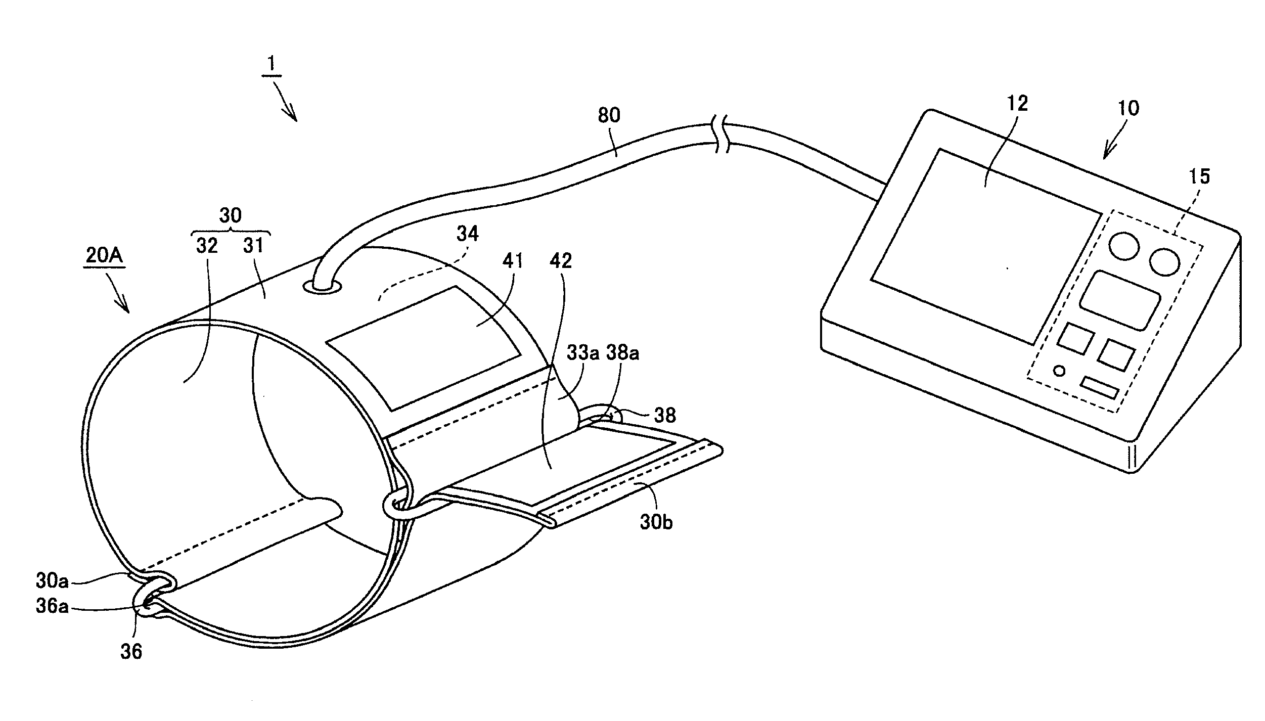
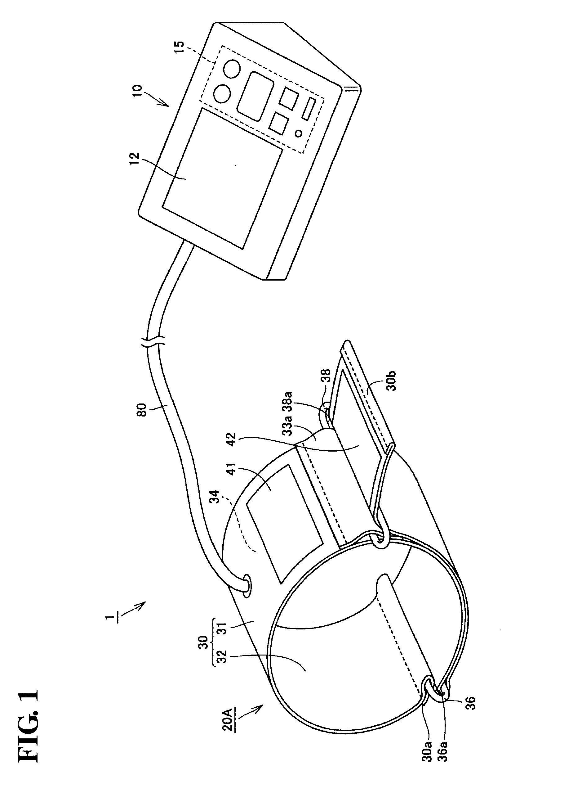
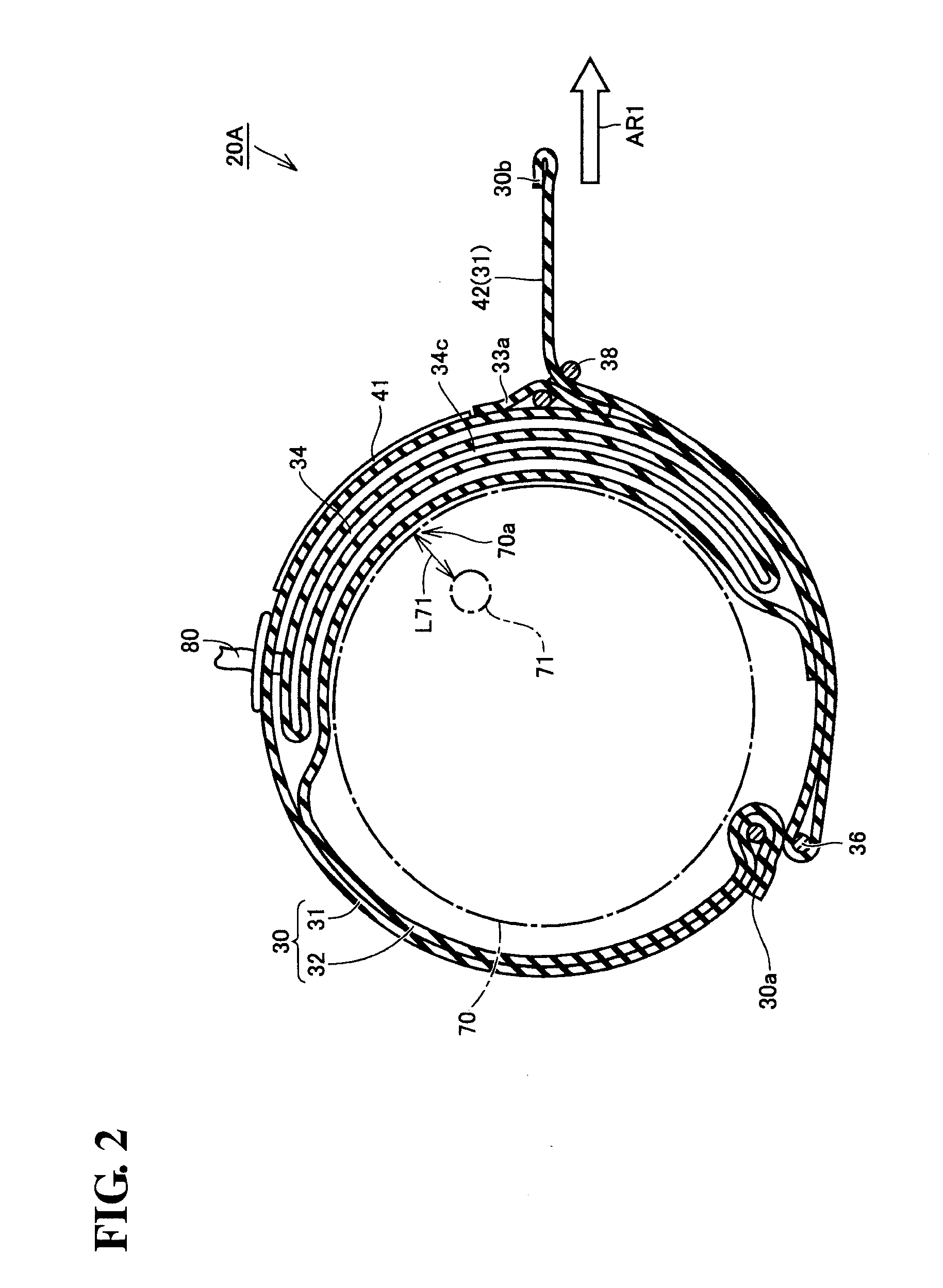
[0046]A sphygmomanometer 1 according to the present embodiment will be described with reference to FIGS. 1 through 7.
[0047]Configuration of Sphygmomanometer 1
[0048]As shown in FIG. 1, the sphygmomanometer 1 includes a main body 10, a cuff 20A, and an air tube 80. The main body 10 is a box-shaped housing. A display unit 12 and an operating unit 15 are provided in the top surface of the main body 10. During measurement, the main body 10 is used by being placed on a table or the like.
[0049]The cuff 20A includes: an outer cover 30; an air bladder 34 (see FIG. 2) that is contained within the outer cover 30 as a fluid bladder; a surface fastener 41 (fastening member); a surface fastener 42; a first loop-shaped ring 36 (first guide member); and a second loop-shaped ring 38 (second guide member).
[0050]The outer cover 30 has a front surface 31 (first main surface), a rear surface 32 (second main surface), one end portion 30a, and another end portion 30b.
[0051]The outer cover 30 is configure...
second embodiment
Variation on Second Embodiment
[0159]A sphygmomanometer according to a variation on the second embodiment will be described with reference to FIGS. 13 and 14. Here, only the differences from the second embodiment will be described.
[0160]As shown in FIG. 13, the difference between the second embodiment and the present variation lies in the other end portion 30b that is passed through the third loop-shaped ring 39 being passed through the second loop-shaped ring 38 once again after being bent back in the third loop-shaped ring 39. The other end portion 30b is passed through the insertion hole of the second loop-shaped ring 38, and is led out toward the outer side from the portion of the outer cover 30 that is formed in the circular shape.
[0161]As shown in FIG. 14, as with the cuff 20B according to the aforementioned second embodiment, the third loop-shaped ring 39 is located between the first loop-shaped ring 36 and the second loop-shaped ring 38 in the lengthwise direction of the oute...
third embodiment
[0172]A sphygmomanometer according to a third embodiment will be described with reference to FIGS. 15 and 16. Here, only the differences from the second embodiment will be described. The difference between the second embodiment and the present embodiment lies in the location where the third loop-shaped ring 39 is attached.
[0173]As shown in FIG. 16, the third loop-shaped ring 39 is located between the second loop-shaped ring 38 and the other end portion 30b of the outer cover 30 in the lengthwise direction of the outer cover 30 when the outer cover 30 is in an unrolled state.
[0174]As shown in FIG. 15, the other end portion 30b of the outer cover 30 that has been passed through the first loop-shaped ring 36 is overlaid along the outer side (the front surface 31 side) of the portion of the outer cover 30 that is formed into a circular shape. The other end portion 30b is passed through the insertion hole of the third loop-shaped ring 39.
[0175]The other end portion 30b of the outer cover...
PUM
 Abstract
Description
Claims
Application Information
 - R&D
- Intellectual Property
- Life Sciences
- Materials
- Tech Scout
- Unparalleled Data Quality
- Higher Quality Content
- 60% Fewer Hallucinations
Browse by: Latest US Patents, China's latest patents, Technical Efficacy Thesaurus, Application Domain, Technology Topic, Popular Technical Reports.
© 2025 PatSnap. All rights reserved.Legal|Privacy policy|Modern Slavery Act Transparency Statement|Sitemap|About US| Contact US: help@patsnap.com


