Antenna Apparatus

a technology of reflectors and antennas, applied in the direction of electrical equipment, radio transmission, transmission, etc., can solve the problems of long time period, dangerous to the life of the operator of the apparatus, and frustrates the operator, so as to achieve efficient and timely

Inactive Publication Date: 2012-12-27
SATCOM TECH
View PDF5 Cites 4 Cited by
  • Summary
  • Abstract
  • Description
  • Claims
  • Application Information

AI Technical Summary

Benefits of technology

[0008]The aim of the present invention is therefore to provide a reflector apparatus which is deployable between storage and in-use positions in an efficient and timely manner.

Problems solved by technology

However, a problem which is experienced is that there can still be a prolonged time period between moving the reflector from a storage position to an in-use position and indeed in returning the reflector from the in-use position to a storage position.
This time period can, at best, be frustrating to the operator of the apparatus and at worst, can be dangerous to the lives of the operator of the apparatus if, for example, the apparatus is being deployed in a hazardous environment such as in a military situation where a prolonged stay at a particular location can increase the likelihood of detection.

Method used


Image

  • Antenna Apparatus
  • Antenna Apparatus
  • Antenna Apparatus

Examples


Embodiment Construction

)

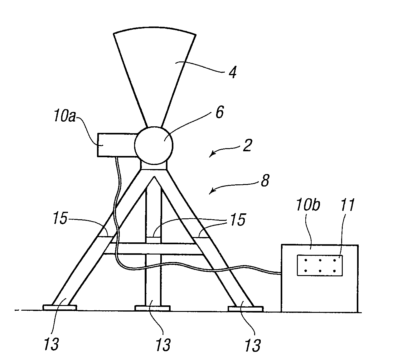
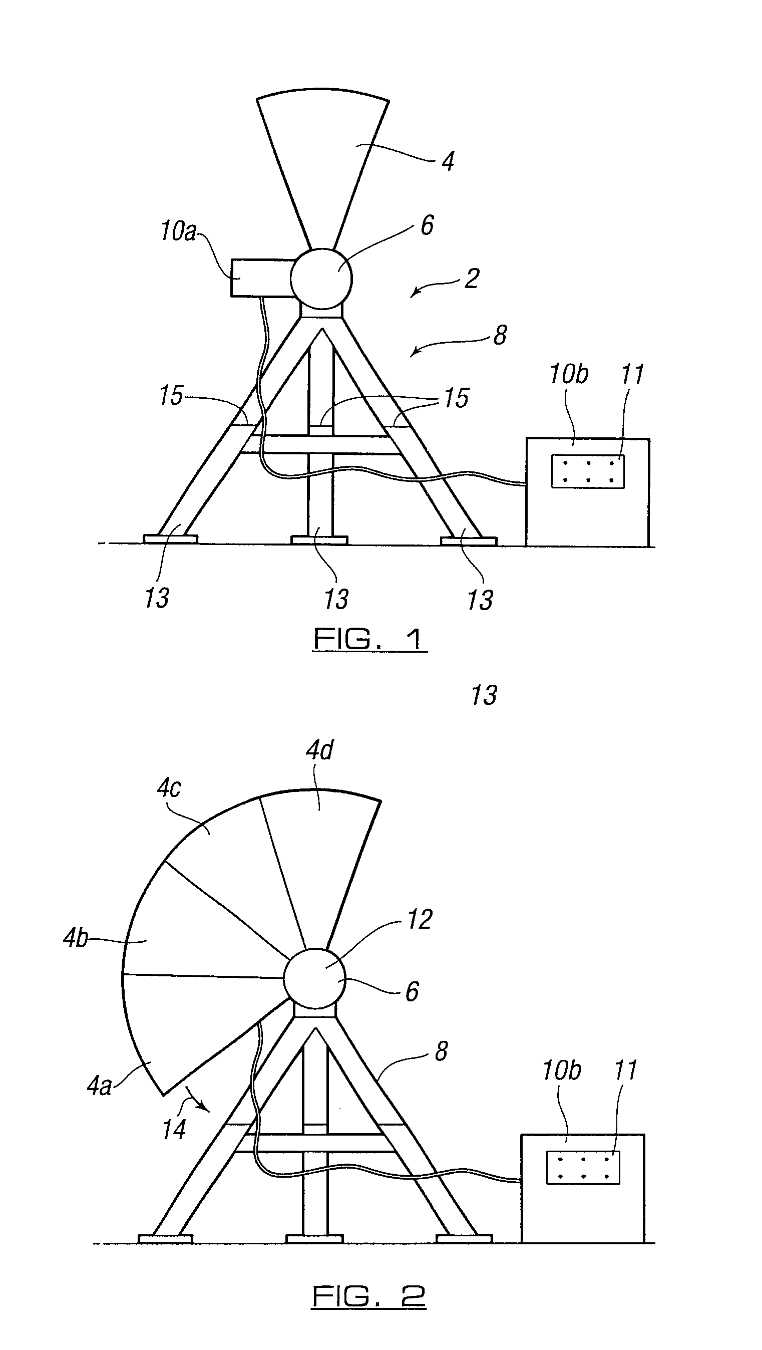
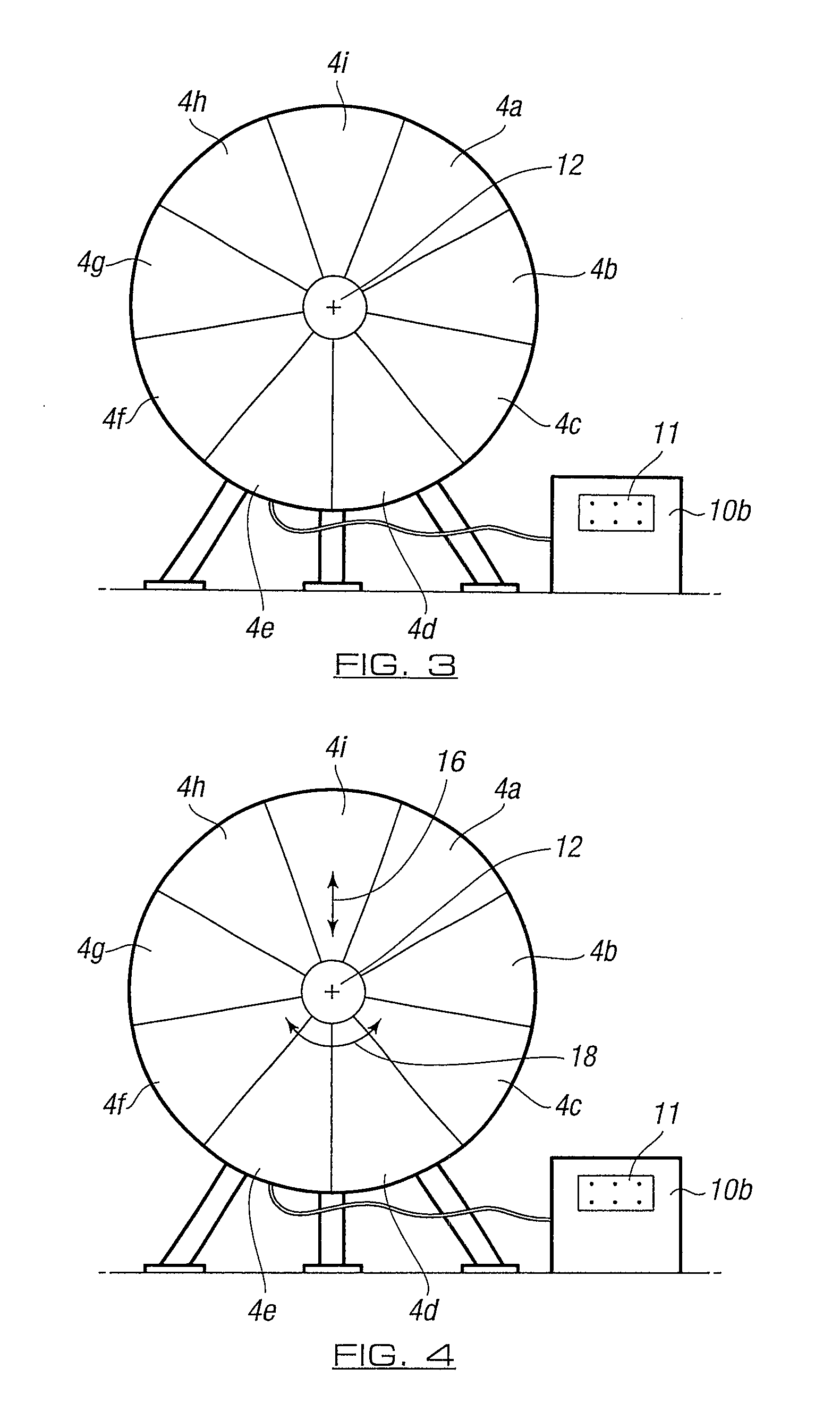
[0033]Referring now to the Figures there is illustrated apparatus 2 including a reflector formed from a plurality of segments 4 which are movable about a central hub 6. The reflector is located on a mounting assembly 8 which can be formed to suit the particular use and location at which the reflector is to be deployed. For example a first form of mounting assembly can be provided for the location of the reflector on a vehicle or building whilst a second form of mounting assembly can be provided for location of the reflector on the ground where the same is provided to be manually transportable.

[0034]The apparatus also includes a drive unit or module 10. The module may be provided entirely located on the mounting assembly or as shown may include a first part 10a including a motor which is connected to the mounting assembly and the reflector segments and a second part 10b which is connectable to the first part but provided separate therefrom as shown. The second part can also include ...


PUM


Abstract

The invention relates to apparatus and a method for the provision of an antenna reflector which is provided in the form of a substantially circular parabolic dish provided to receive and/or transmit signals over known frequency ranges. The reflector can be moved between storage and in-use positions by the movement of segments of the reflector manually, but more typically by drive means connected thereto. The apparatus can also be provided with alignment means which allow the reflector to be positioned to receive signals from a known satellite when at a particular known location. The invention allows the use of a reflector to be achieved quickly and efficiently in potentially hazardous geographical locations.

Description

CROSS-REFERENCE TO RELATED APPLICATIONS[0001]This United States patent application claims priority to British Patent Application No. 1110521.0 filed 22 Jun. 2011 which is incorporated herein by reference.BACKGROUND OF THE INVENTION[0002]The invention to which this application relates is to a collapsible reflector or antenna, hereinafter referred to as a reflector, of a type which can be used to receive and / or transmit digital data, with the reflector being used at a particular location to be in communication with one or more satellites in space via which the digital data is transmitted to or from a remote location.[0003]The provision of parabolic reflectors which may typically be parabolic or of another shaping to suit the specific requirements is well known and, most typically, the same are provided at a fixed location such as the roof or wall of a building, and, when positioned on the roof or wall of a building at the fixed position the same are aligned so as to provide the optimu...

Claims


Application Information

Patent Timeline
Patent Type & Authority Applications(United States)
IPC IPC(8): H04B7/185H01Q3/20
CPCH01Q15/162
Inventor GEEN, DAVID
Owner SATCOM TECH
Why Eureka
Try Eureka