LED light shade for secondary light emission

Inactive Publication Date: 2012-12-27
CHIANG KEN SHENG
View PDF7 Cites 0 Cited by
  • Summary
  • Abstract
  • Description
  • Claims
  • Application Information

AI Technical Summary

Benefits of technology

[0005]The invention is advantageous in that it provides a LED light shade, which substantially enhances the light intensity from the LED light source and evenly distributes the LED light when the LED light passes through the LED light shade.
[0007]According to the present invention, the foregoing and other objects and advantages are attained by a LED light shade for a LED light source, comprising a shade body arranged for LED light projecting thereto, and a light enhancing layer provided at the shade body, wherein the light enhancing layer comprises a mixture of fluorescent powder and pearlescent powder. The fluorescent powder can be in form of phosphor layer. Mixing the pearlescent with the fluorescent powder is to enhance the light efficiency of the secondary light emission when the LED light hits the light enhancing layer at the shade body. The light enhancing layer can be either integrated at an inner surface of the shade body or coated at an outer surface of the shade body.
[0010]In accordance with the invention, the light enhancing layer can be integrally formed with the material of the shade body or can be coated on the surface of the shade body, wherein when the LED light source is electrified, the LED light source will generate LED light with a wavelength matching with the corresponding wavelength of light enhancing layer, such that the light enhancing layer is activated to enable a secondary light emission at the shade body so as to enhance the light intensity of the LED light. In other words, the wavelength of the fluorescent powder matches to the wavelength of the LED light from the LED light source to generate a secondary light emission. Therefore, the light enhancing layer enables the secondary light emission that significantly increases the brightness / produce more lumens to offer the possibility of further power savings to produce the same lumens as a higher powered light. Accordingly, the light intensity of the LED light can increase at least 30% through the light enhancing layer. According to the test result, the present invention increases more than 50% of the conventional LED light apparatus. In addition, the LED light will be evenly distributed through the surface of the shade body via the light enhancing layer. Therefore, the LED light shade can be considered as an energy saving and environment friendly product.
[0011]It is appreciated that different pigments of fluorescent powder and pearlescent powder can be mixed to form the light enhancing layer, such that the LED light shade is adapted to generate a light effect, such as different colors, when incorporating with the LED light source. In other words, the LED light shade can be incorporated to form any LED light apparatus, such as fluorescent tube, LED light bulb, or LED lamp, to generate different light effects so as to enhance the aesthetic appearance of the LED light apparatus.

Problems solved by technology

In addition, the interior structural design of the LED light apparatus cannot be seen through the casing with the light diffusion agent, such that the casing cannot keep the aesthetic appearance of the LED light apparatus.

Method used


Image

  • LED light shade for secondary light emission
  • LED light shade for secondary light emission
  • LED light shade for secondary light emission

Examples


second embodiment

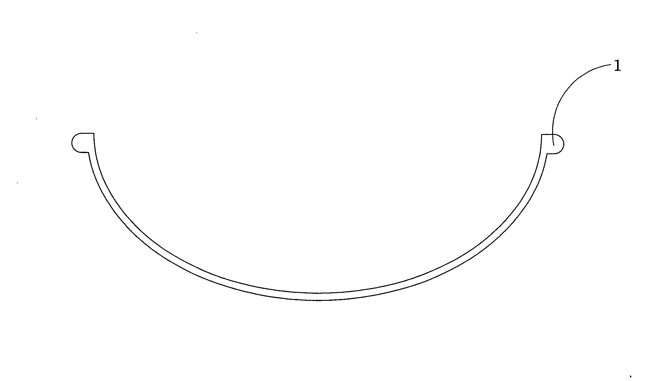
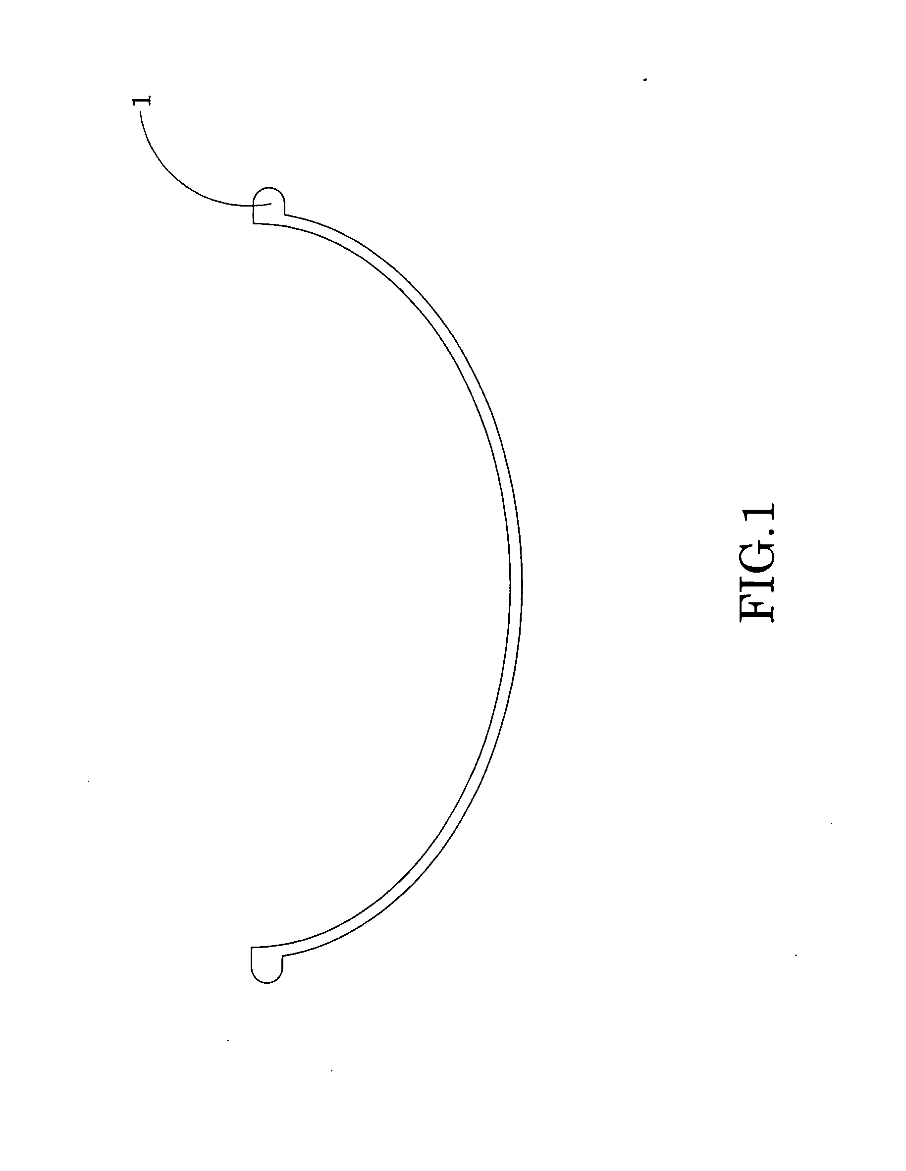
[0019]FIG. 1 also illustrates the LED light shade, the base material of the shade body 1, fluorescent powder and pearlescent powder are well-mixed to form the shade body 1.

[0020]Preferably, the ratio of the mixture of fluorescent powder and pearlescent powder is that the 90 parts of fluorescent powder and 10 parts of pearlescent powder.

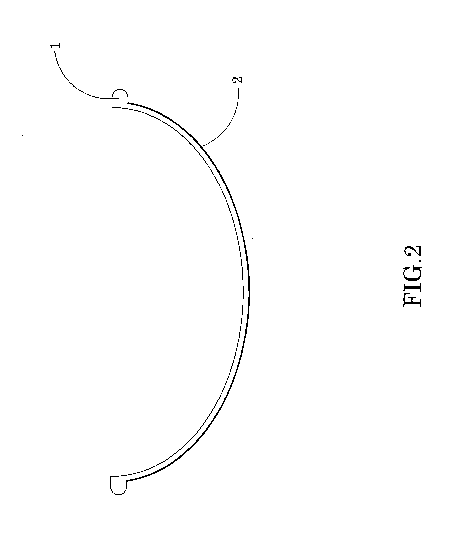
[0021]Alternatively, the ratio of the mixture of base material of the shade body 1 and the light enhancing layer is that the 70 parts of the base material of the shade body 1 and 30 parts of the light enhancing layer.

third embodiment

[0022]FIG. 1 also illustrates the LED light shade, the base material of the shade body 1, fluorescent powder and pearlescent powder are well-mixed to form the shade body 1.

[0023]Preferably, the ratio of the mixture of fluorescent powder and pearlescent powder is that the 100 parts of fluorescent powder and 0 parts of pearlescent powder. In other words, the light enhancing layer only contains fluorescent powder.

[0024]Alternatively, the ratio of the mixture of base material of the shade body 1 and the light enhancing layer is that the 50 parts of the base material of the shade body 1 and 50 parts of the light enhancing layer.

fourth embodiment

[0025]FIG. 1 also illustrates the LED light shade, the base material of the shade body 1, fluorescent powder and pearlescent powder are well-mixed to form the shade body 1.

[0026]Preferably, the ratio of the mixture of fluorescent powder and pearlescent powder is that the 100 parts of fluorescent powder and 0 parts of pearlescent powder. In other words, the light enhancing layer only contains fluorescent powder.

[0027]Alternatively, the ratio of the mixture of base material of the shade body 1 and the light enhancing layer is that the 70 parts of the base material of the shade body 1 and 30 parts of the light enhancing layer.


PUM

PropertyMeasurementUnit
Fractionaaaaaaaaaa
Fractionaaaaaaaaaa
Fractionaaaaaaaaaa

Abstract

A LED light shade includes a shade body and a light enhancing layer integrated with a base material of the shade body. Alternatively, the light enhancing layer is coated on a surface of the shade body. When a LED light source is electrified, the LED light source generates LED light with a wavelength matching with the corresponding wavelength of light enhancing layer, such that the light enhancing layer is activated to enable a secondary light emission at the shade body so as to enhance the light intensity of the LED light. The light enhancing layer enables a secondary light emission that significantly increases the 30% brightness to produce the same lumens as a higher powered light. The LED light is evenly distributed through the shade body via the light enhancing layer. Therefore, the LED light shade is considered as an energy saving and environment friendly product.

Description

BACKGROUND OF THE PRESENT INVENTION[0001]1. Field of Invention[0002]The present invention relates to a LED apparatus, and more particular to a LED light shade which substantially enhance the light intensity from the LED light source to generate a secondary light emission when the LED light passes through the LED light shade.[0003]2. Description of Related Arts[0004]LED light apparatus is considered as an environmental light product to replace the conventional light bulb apparatus because LED light apparatus has a relatively long service life span, high light effect, no radiation emission, high shock resistance, and low energy consumption. Generally speaking, the conventional light apparatus, such as the LED lamp or LED light bulb, comprises a LED light source enclosed by a casing, wherein the casing is made of transparent material or composed of a light diffusion agent for diffusing the light from the LED light source. Accordingly, the casing with the light diffusion agent will redu...

Claims


Application Information

Patent Timeline
IPC IPC(8): F21V9/16F21V9/40
CPCF21K9/56F21Y2101/02F21V3/0481F21V9/16F21V3/0409F21K9/64F21V1/17F21V3/06F21V3/12F21Y2115/10
Inventor CHIANG, KEN-SHENG
Owner CHIANG KEN SHENG
Why Eureka
Try Eureka