

Methods and apparatus for treatment of hollow anatomical structures
- Summary
- Abstract
- Description
- Claims
- Application Information
AI Technical Summary
Benefits of technology
Problems solved by technology
Method used
Image

Examples
second embodiment
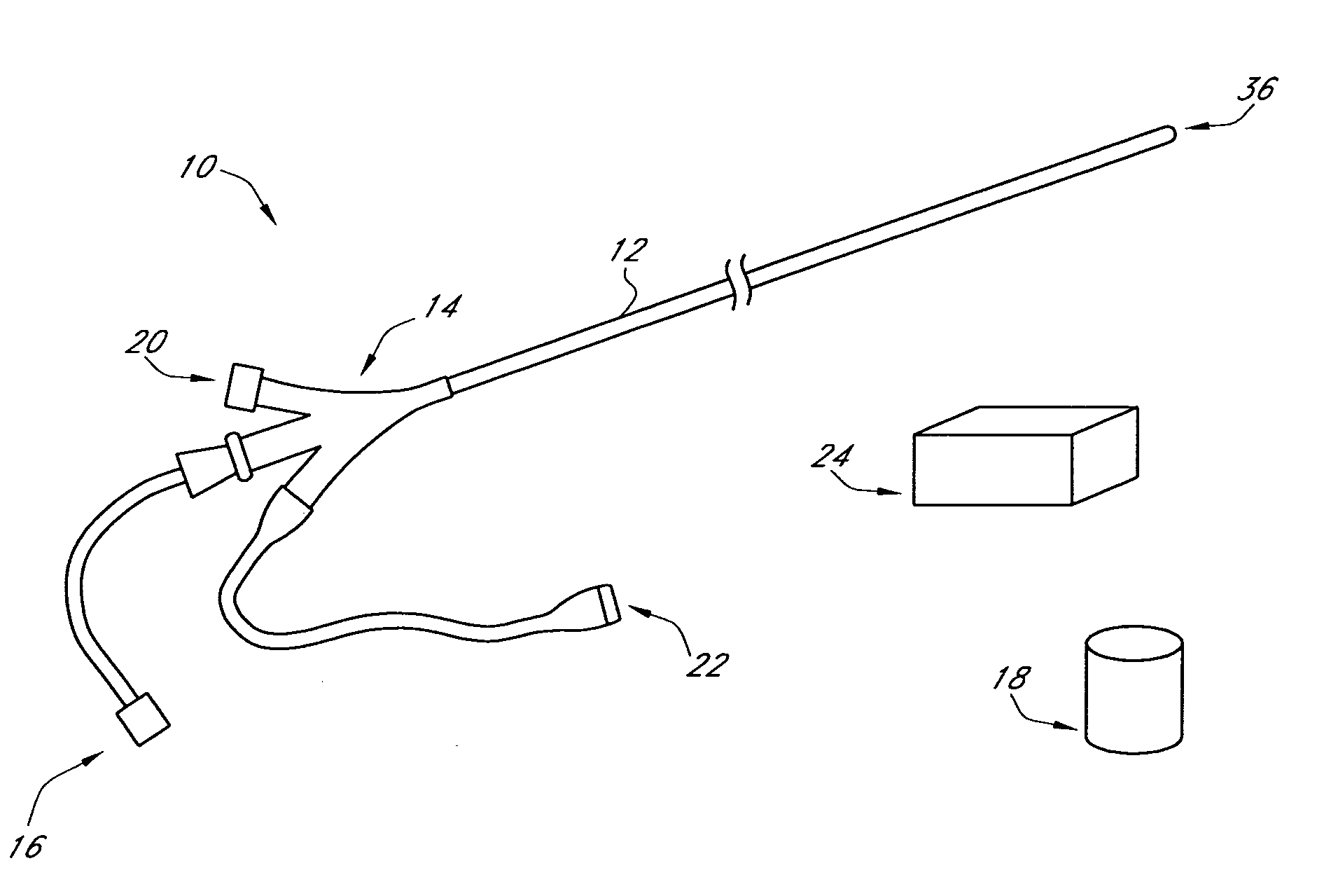
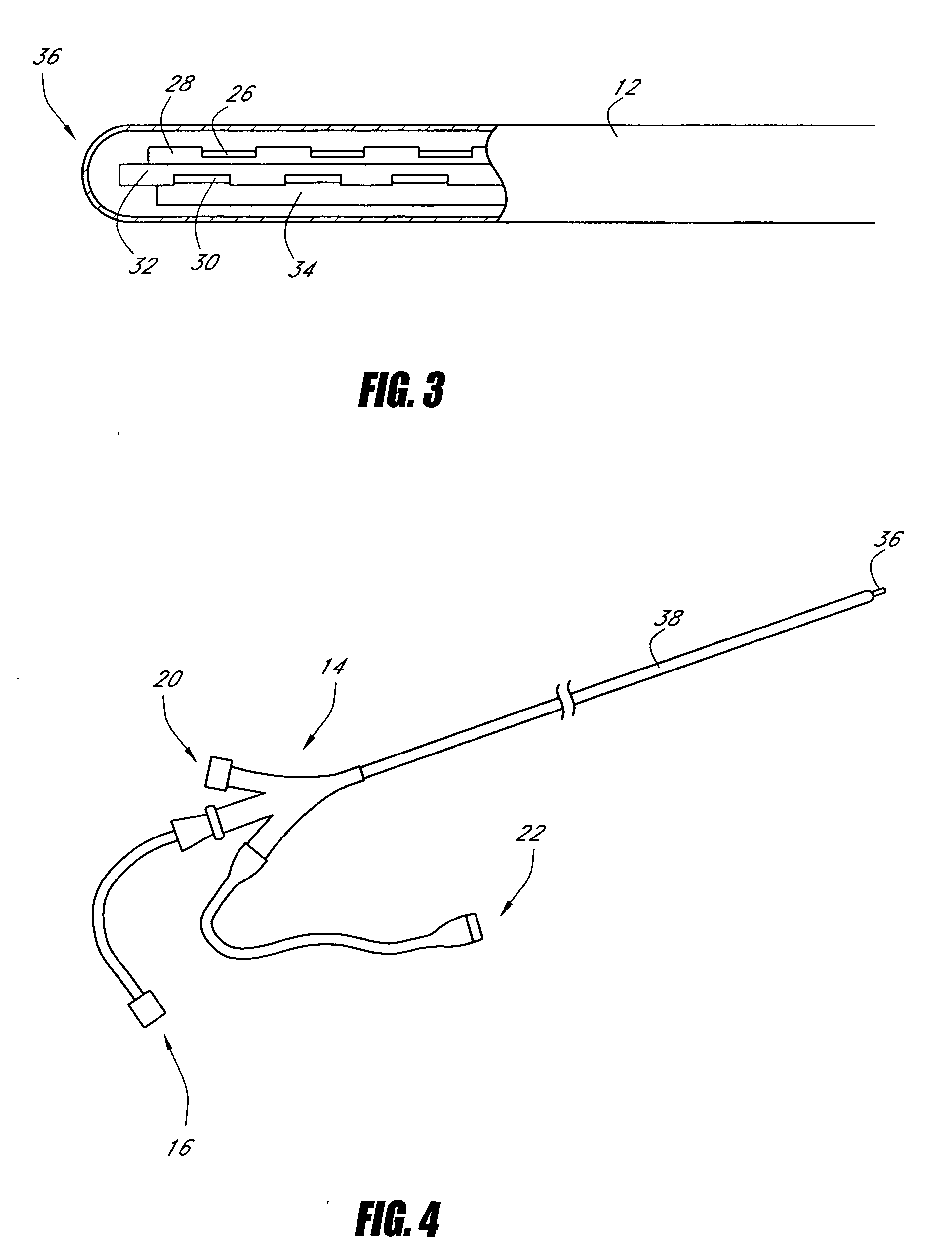
[0126] the catheter, depicted in FIGS. 4 and 5, may be generally similar to the embodiment depicted in FIGS. 1-3, except as further described herein. The embodiment of FIGS. 4-5 employs a coiled catheter shaft 36 to facilitate apposition with the HAS wall. The embodiment of FIGS. 4 and 5 may be particularly useful in situations where external compression (such as manual, Esmark, or Tumescent Anesthesia) of the HAS or other methods are insufficient to cause the HAS diameter to reduce sufficiently to appose a fixed-diameter catheter. The coiled configuration may comprise an open helix or corkscrew, and can be made from a deformable material like pebax, polyimide, polyethylene or silicone. The helical shape can also be obtained by using a shaped spine or wire made from nickel-titanium, stainless-steel or other materials with similar characteristics.
[0127] An outer sheath 38 can be used to enclose and straighten the coiled catheter shaft 36 for introduction into and advancement through ...
embodiment 870
[0268]FIG. 47 shows another embodiment 870 of the device of FIG. 45. The spline sets 874 are arranged for bipolar RF. In this embodiment, each electrode spline set 874 has a different polarity from an adjacent electrode spline set.
[0269] The embodiments illustrated in FIGS. 45-47 can be used in conjunction with the multiplexer process when used in a stationary manner.
[0270] With reference to FIG. 48, in one embodiment the device 900 has expandable-cantilevered electrodes 902 similar to those described above. The device has one or more electrodes 902 in one or more sets of electrodes 904. Proximal to the electrode sets 904 is a sheath-mounted heating element 908 (e.g., a resistive coil). The proximal heating coil preferably initiates the treatment process and the expanded electrodes preferably complete the treatment process. The effective length of the proximal coil element can be controlled by the use of a sheath component similar to that described above with reference to FIG. 37. ...
first embodiment
[0314]FIG. 69 shows the catheter design with a distal portion 1209 that transfers the energy directly to the HAS when expanded. In this configuration, the distal portion is pre-formed into a planar serpentine shape that stretches the opposing walls of the HAS outward until the top & bottom are forced together and collapsed onto the distal portion. In this expanded shape, the device can be at, for example, a minimum planar thickness range of 2 Fr to 10 Fr (0.66 mm to 3.3 mm) and maximum width range of 3 mm to 25 mm. The intent is to expand and flatten the HAS to approximately the thickness or diameter of the catheter distal portion. An example of a serpentine section is a device distal portion which is 4 Fr or 1.33 mm in diameter with a possible expansion width of 20 mm. A specific example would be to place a 5 Fr or 1.67 mm diameter device in a 8 mm diameter vein. The device then expands and in turn decreases the top to bottom height of the HAS from 8 mm down to 1.67 mm or about a 3...
PUM
 Abstract
Description
Claims
Application Information