
Slide cover lifting structure

a technology of sliding cover and lifting structure, which is applied in the direction of portable computers, instruments, manufacturing tools, etc., can solve the problems of unfavorable tablet computer fabrication, prone to spring back, and the size of the hinges must be relatively increased to avoid spring back

Active Publication Date: 2012-12-27
LIANHONG TECH
View PDF13 Cites 31 Cited by
  • Summary
  • Abstract
  • Description
  • Claims
  • Application Information

AI Technical Summary

Benefits of technology

[0009]The present invention has been accomplished under the circumstances in view. It is main object of the present invention to provide a slide cover lifting structure for use in an electronic device comprising a cover panel and a base member, which eliminates the drawbacks of the aforesaid prior art design.
[0012]The slide cover lifting further comprises two first rollers respectively pivotally mounted in the base member at two opposite lateral sides and two second rollers respectively pivotally mounted in the cover panel at two opposite lateral sides, the first rollers and the second rollers being adapted to maintain a constant gap between the cover panel and the base member, and two slanted grooves respectively formed in the base member in the sliding path of the first rollers at the cover panel for enabling the constant gap to be kept between the cover panel and the base member when the cover panel is lifted from the base member. Each slanted groove comprises two half moon shaped groove portions for enabling the cover panel to be positively positioned in one of an open position and a close position.

Problems solved by technology

This accommodation chamber limits the utilization of the internal circuit board space of the base member, causing unfavorable effects on tablet computer fabrication.
Further, because the hinges that are provided at the cover panel to provide torque are kept apart at a long distance, they tend to spring back when the cover panel is lifted.
In this prior art design, there is no any other support design, and therefore the size of the hinges must be relatively increased to avoid spring back, not in conformity with compacting design.
However friction between the spring plates and the sliding rails will cause surface damage.

Method used


Image

  • Slide cover lifting structure
  • Slide cover lifting structure
  • Slide cover lifting structure

Examples


Embodiment Construction

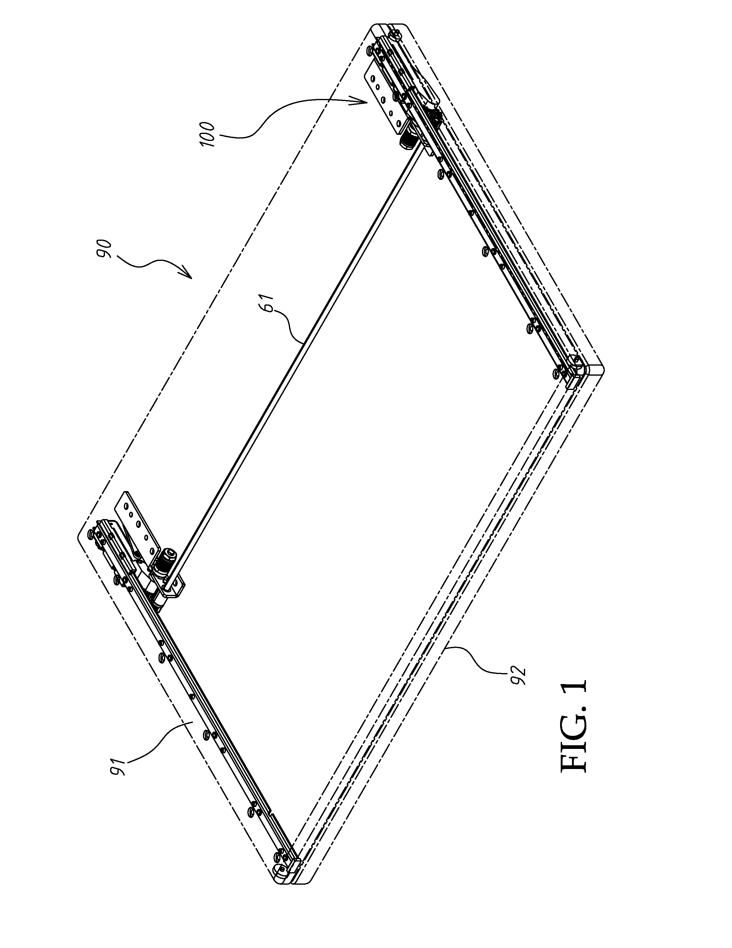
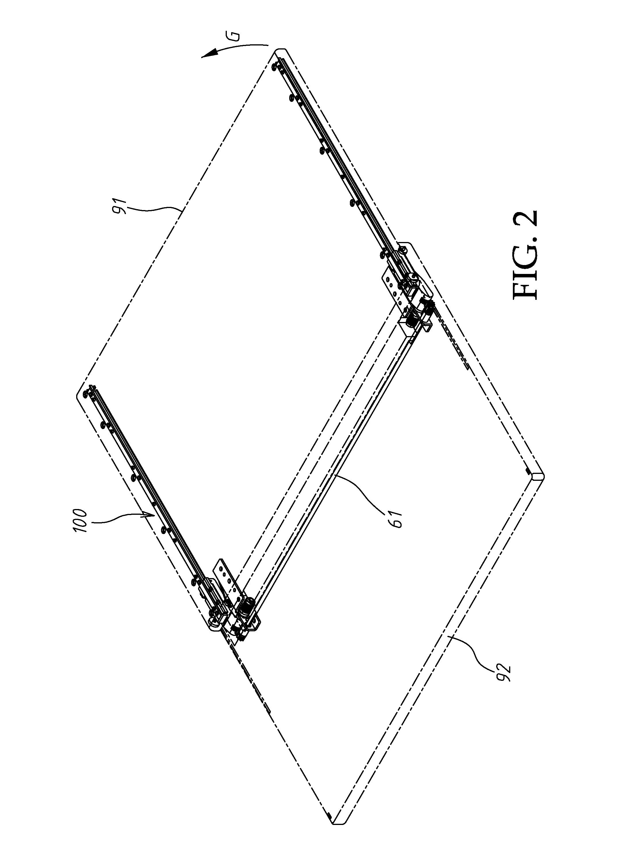
[0034]Referring to FIGS. 1˜3, a slide cover lifting structure 100 in accordance with the present invention is shown used in an electronic device 90 comprising a cover panel 91 and a base member 92. The electronic device 90 can be, for example, a tablet computer. The cover panel 91 is a LCD display panel. The base member 92 is the operating system end of the electronic device 90, comprising a keyboard. When opening the cover panel 91, move the cover panel 91 horizontally relative to the base member 92 (see FIG. 2), and then bias the cover panel 91 to a tilted position relative to the base member 92 (see FIG. 3).

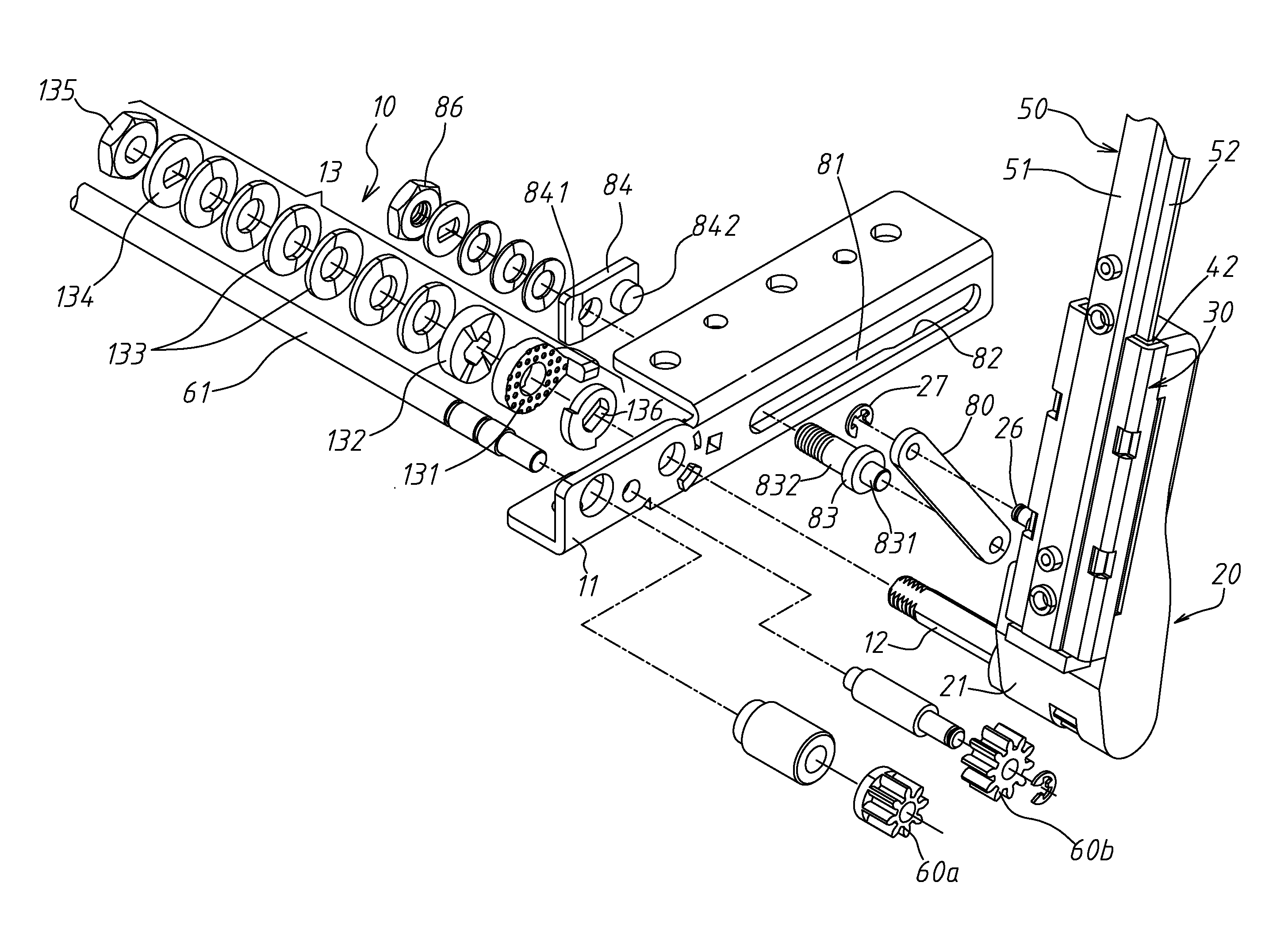
[0035]Referring to FIGS. 4˜8, the slide cover lifting structure 100 comprises a pair hinges 10, a pair of sliding rail holders 20, a pair of bearing members 30, a pair of plastic slide guides 40, a pair of sliding rails 50, two gear sets 60 and a pair of gear racks 70. These component pairs are symmetrically mounted on two distal ends of a transmission shaft 61.

[0036]The hinge...


PUM


Abstract

A slide cover lifting structure used in an electronic device consisting of a base member and a cover panel is disclosed to include a pair hinges, a pair of sliding rail holders, a pair of bearing members, a pair of plastic slide guides, a pair of sliding rails, a transmission shaft, two gear sets and a pair of gear racks. The gear sets are provided between the sliding rail holders and the bearing members for transmission of applied force. The transmission shaft is mounted in the base member (system end), allowing free utilization of the internal circuit board space of the base member.

Description

BACKGROUND OF THE INVENTION[0001]1. Field of the Invention[0002]The present invention relates to slide cover mounting technology and more particularly, to a slide cover lifting structure for use in an electronic device, for example, tablet computer, in the transmission shaft which enables the top cover panel of the electronic device to be moved smoothly and stably in horizontal relative to the base panel of the electronic device and then lifted from a horizontal position to a tilted position is kept in the base member of the electronic device.[0003]2. Description of the Related Art[0004]There are tablet computers that comprise an operating system end arranged at the bottom side of a LCD display panel in such a manner that the LCD display panel can be moved horizontally relative to the operating system end and then lifted to a tilted position so that the user can use the keyboard on the operating system end. To satisfy this operation, a special slide cover mounting arrangement is nec...

Claims


Application Information

Patent Timeline
IPC IPC(8): F16C29/02
CPCG06F1/1616G06F1/1624G06F1/1681Y10T16/544Y10T16/541Y10T16/547Y10T16/54025
Inventor CHEN, CHIA HUILIN, CHE-HSIENHU, PO-HSIANG
Owner LIANHONG TECH
Learn More