Knee joint prosthesis

a knee joint and prosthesis technology, applied in the field of knee joint prosthesis, can solve the problems of increasing the difficulty level of changing the knee joint prosthesis, and achieve the effect of easy chang

Inactive Publication Date: 2012-12-27
CHEN CHIEN WEN +1
View PDF2 Cites 11 Cited by
  • Summary
  • Abstract
  • Description
  • Claims
  • Application Information

AI Technical Summary

Benefits of technology

[0005]The object of this invention is to provide a safety knee joint prosthesis that can be changed easily between an elevated position and a flexed position.
[0006]According to this invention, a knee joint prosthesis is adapted for interconnecting a prosthetic lower leg and a prosthetic thigh. The knee joint prosthesis includes a knee seat adapted to be disposed under and connected to the prosthetic thigh, a connecting seat adapted to be disposed above and connected to the prosthetic lower leg, a link assembly, and an adjusting unit. The link assembly includes a plurality of links each connected pivotally to the knee seat and the connecting seat in such a manner to permit the knee joint prosthesis to change between an elevated position and a flexed position. The adjusting unit is disposed in the knee seat, and is operable to cooperate with the link assembly to adjust difficulty level of changing the knee joint prosthesis between the elevated and flexed positions.

Problems solved by technology

However, such a design increases the difficulty level of changing the knee joint prosthesis between an elevated position and a flexed position.

Method used


Image

  • Knee joint prosthesis
  • Knee joint prosthesis
  • Knee joint prosthesis

Examples


Embodiment Construction

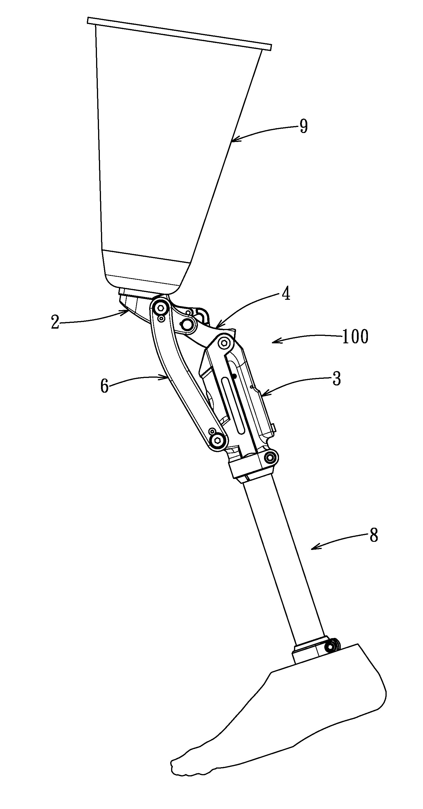
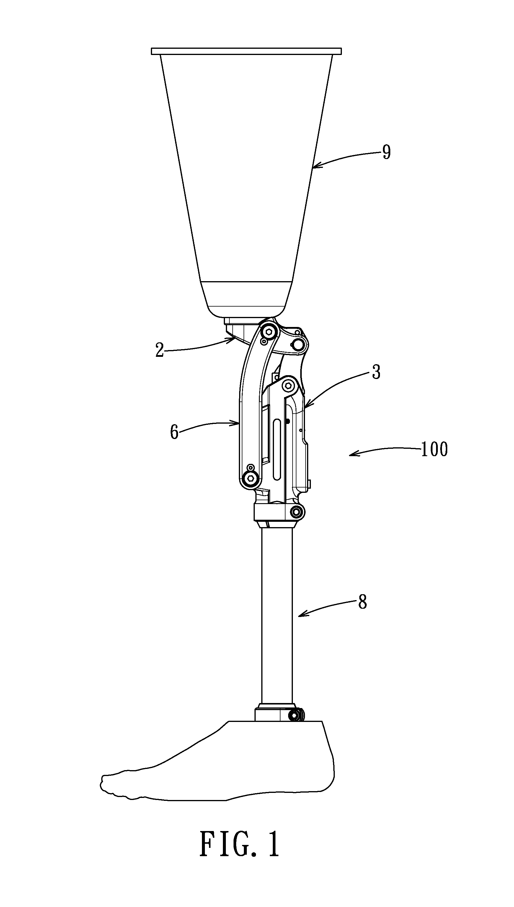
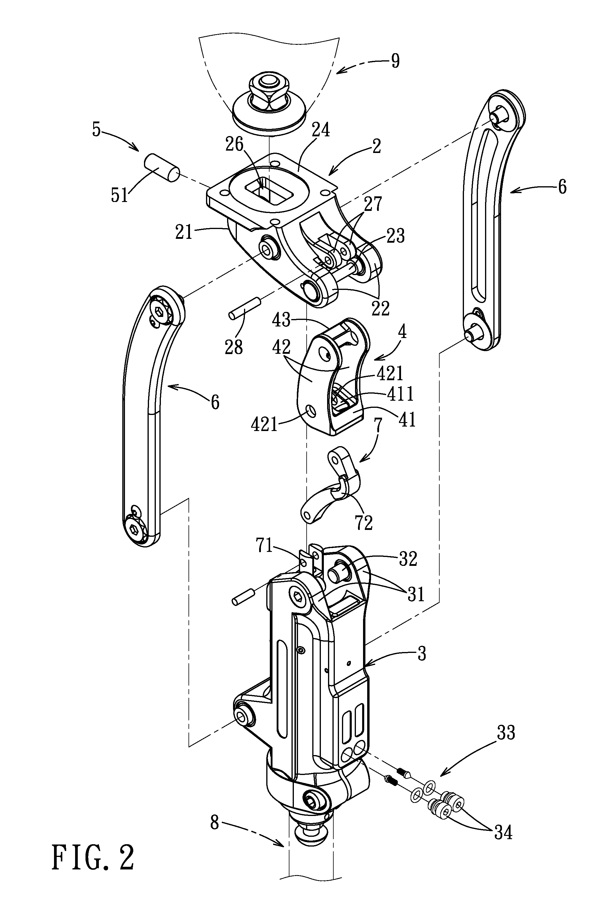
[0014]Referring to FIGS. 1 and 2, the preferred embodiment of a knee joint prosthesis 100 according to this invention forms a portion of a leg prosthesis, and is used to interconnect a prosthetic thigh 8 and a prosthetic lower leg 9. The knee joint prosthesis 100 includes a knee seat 2 disposed below and connected to the prosthetic thigh 9, a connecting seat 3 disposed above and connected to the prosthetic lower leg 8, a link assembly consisting of a rear link 4 and two front links 6, and an adjusting unit 5.

[0015]With further reference to FIG. 4, the knee seat 2 includes a seat body 21 connected to the prosthetic thigh 9, two parallel arms 22 extending rearwardly and downwardly from the seat body 21 and spaced apart from each other in a left-to-right direction, and a pivot pin 23 extending through lower end portions of the arms 22. The seat body 21 has a top wall 24, and a receiving hole 25 formed through the seat body 21. The top wall 24 has a slide slot 26 formed therethrough and...


PUM


Abstract

A knee joint prosthesis is adapted for interconnecting a prosthetic lower leg and a prosthetic thigh. The knee joint prosthesis includes a knee seat disposed under and connected to the prosthetic thigh, a connecting seat disposed above and connected to the prosthetic lower leg, a link assembly, and an adjusting unit. The link assembly includes a plurality of links each connected pivotally to the knee seat and the connecting seat in such a manner to allow the knee joint prosthesis to change between an elevated position and a flexed position. The adjusting unit is disposed in the knee seat, and is operable to cooperate with the link assembly to adjust difficulty level of changing the knee joint prosthesis between the elevated and flexed positions.

Description

BACKGROUND OF THE INVENTION[0001]1. Field of the Invention[0002]This invention relates to a prosthetic device, and more particularly to a knee joint prosthesis.[0003]2. Description of the Related Art[0004]To meet the safety requirements, a conventional knee joint prosthesis is designed to have a strong support when it is flexed. However, such a design increases the difficulty level of changing the knee joint prosthesis between an elevated position and a flexed position. Hence, it is desirable that a knee joint prosthesis has the advantages of enhanced safety and low difficulty level of changing between the elevated position and the flexed position.SUMMARY OF THE INVENTION[0005]The object of this invention is to provide a safety knee joint prosthesis that can be changed easily between an elevated position and a flexed position.[0006]According to this invention, a knee joint prosthesis is adapted for interconnecting a prosthetic lower leg and a prosthetic thigh. The knee joint prosthe...

Claims


Application Information

Patent Timeline
Patent Type & Authority Applications(United States)
IPC IPC(8): A61F2/62
CPCA61F2/644A61F2/76A61F2002/5006A61F2002/5073A61F2002/5021A61F2002/5033A61F2002/5043A61F2002/5007
Inventor CHEN, CHIEN-WENCHEN, CHIEN-CHENG
Owner CHEN CHIEN WEN
Why Eureka
Try Eureka