
Stabilisation of Objects

a technology for stabilizing objects and objects, applied in the field of objects stabilizing, can solve problems such as rocking and unstable tables

Inactive Publication Date: 2013-01-03
NO ROCK CAFE TABLES
View PDF7 Cites 10 Cited by
  • Summary
  • Abstract
  • Description
  • Claims
  • Application Information

AI Technical Summary

Benefits of technology

The invention is a design for a compact and efficient interconnection means that allows for the rotation of two legs around their pivot axis. The pivots of neighboring legs are located between their pivot axes, making the interconnection means small and cost-effective. Additionally, a travel limit is provided to restrict how far the legs can rotate, preventing any unwanted movement or warp displacement. Overall, the design allows for a compact, efficient, and stable interconnection means.

Problems solved by technology

However, there are many reasons why three legs are undesirable on many objects, particularly those having a quadrilateral shape in plan view such as square or rectangular topped tables where four legs are generally preferred, located towards each corner, with more than four legs occasionally being desired or even required for larger tables.
This causes the table to be unstable and rock, which is most noticeable in four-legged tables with small table tops.

Method used


Image

  • Stabilisation of Objects
  • Stabilisation of Objects
  • Stabilisation of Objects

Examples


Embodiment Construction

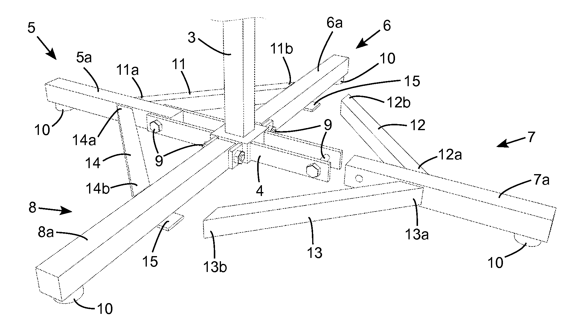
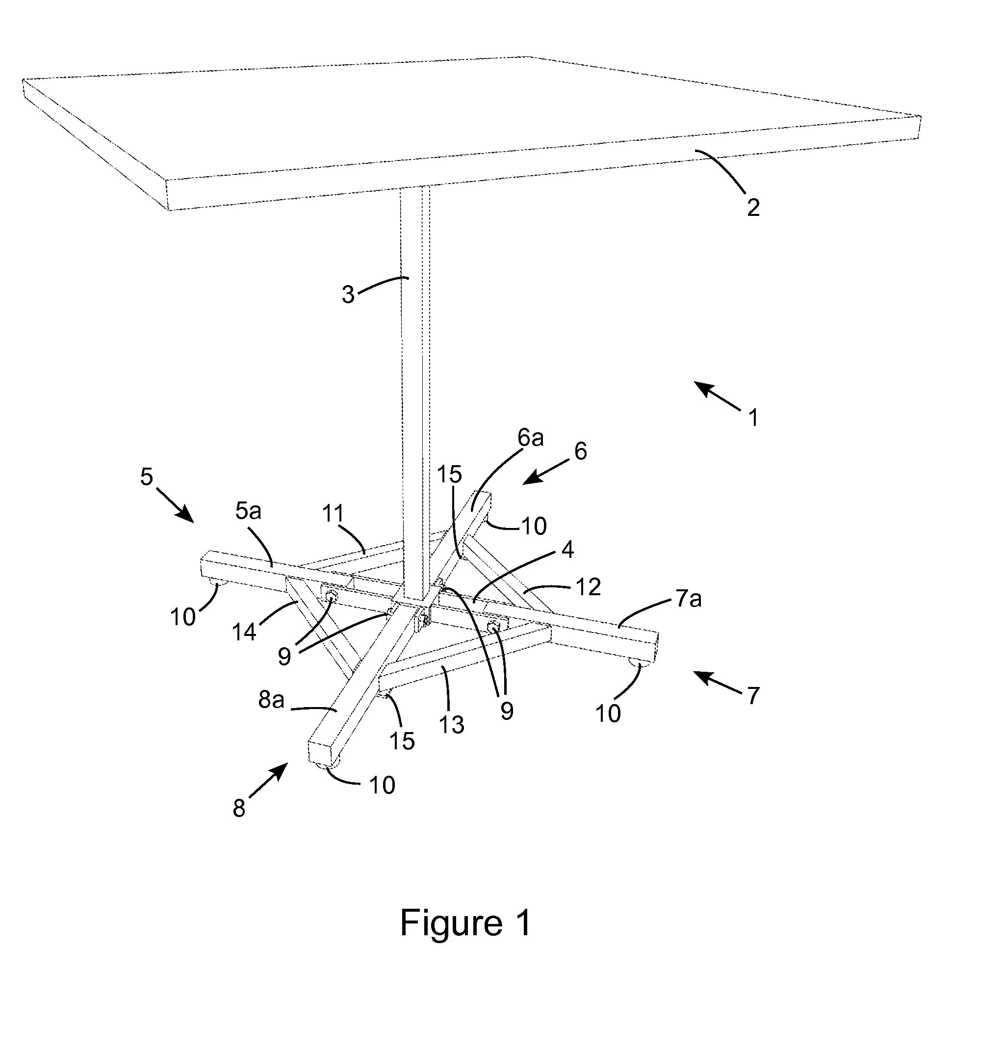
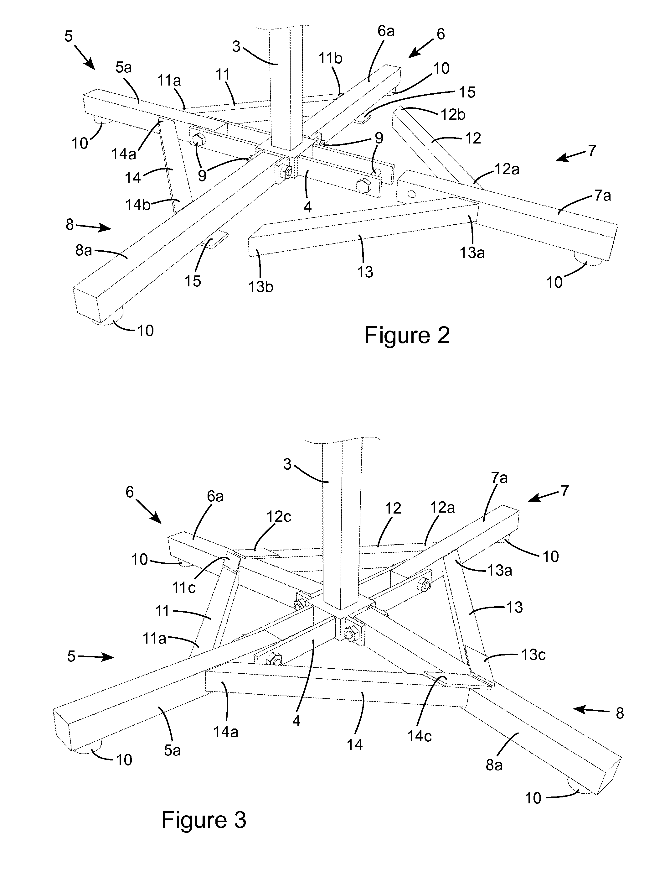
[0043]Referring initially to FIG. 1 there is shown a table 1 having a table top 2 supported by a stem or vertical member 3. The lower end of the stem is attached to a base portion 4 to which four table legs 5, 6, 7 and 8 are connected. The legs are shown in two opposing pairs, each leg including a beam portion 5a, 6a, 7a or 8a, being pivotally connected to the base portion 4 by a corresponding bolt 9. A foot10 is shown on each leg for engaging with the ground. Each foot can be integral with the leg, being a simple as a flat or preferably slightly convex surface to contact the ground, or it can be a separately attached item to allow the foot to be suited to the application (for example a different ground contacting material such as rubber or felt can be bonded to the leg or attached as a replaceable part). Extending between the beam portion of each pair of adjacent legs is a protrusion (or lever or balance portion) 11, 12, 13, or 14. Two of the protrusions (11 and 14) are fixed to on...


PUM


Abstract

A support mechanism for supporting an object, such as a table, has at least four legs (5-8) and an interconnection means (4) connecting the legs. Each leg has at least a beam portion (5a-8a) with an inner (proximal) end and an outer (distal) end. The beam portion of each leg is connected to the interconnection means by a respective pivot (9) having a pivot axis. The pivot is located between the inner and outer ends of the beam portion. Each respective pair of adjacent legs has a protrusion (or lever or balance portion) (11-14), each fixed to one leg of said pair of adjacent legs and extending from that one leg to act on the other leg of said pair of adjacent legs whereby a support reaction force is transmitted between the pair of adjacent legs at a point on the other leg between the pivot and the outer end of the beam portion of that other leg. Said point is on the opposite side of the pivot axis of the one leg to the outer end of the beam portion of that one leg. In use, the outer end of the beam portion of one leg moves in an upwards direction and the outer end of the beam portion of the other leg of the adjacent pair of legs moves in a downwards direction. Feet (10) can be replaced, or the beam portions (5a-8a) can be extended, by downwards extending portions (5b,6b,7b and 8b) connected to the outer ends of the beam portion of each leg.

Description

FIELD OF THE INVENTION[0001]The present invention relates to the stabilisation of objects, such as freestanding furniture and appliances.BACKGROUND TO THE INVENTION[0002]Many objects such as items of furniture (ie tables, chairs and benches) and white goods are supported at at least four points of contact with the ground or floor (e.g. using ground engaging means such as legs, feet or wheels). These objects are used in a wide range of situations and in many cases the surface on which the object is stood is uneven or not a perfectly flat plane. To prevent, for example, furniture from rocking on an uneven surface it is common for small tables or stools to use three legs since three points are sufficient to define a linear plane and therefore provide location of the object without rocking. However, there are many reasons why three legs are undesirable on many objects, particularly those having a quadrilateral shape in plan view such as square or rectangular topped tables where four leg...

Claims


Application Information

Patent Timeline
IPC IPC(8): A47B91/16A47B9/16
CPCA47B13/02F16M7/00A47B91/16
Inventor HEYRING, CHRISTOPHER BRIANBEAMES, JONATHAN RAMSEYCATONI, JOHN GERARDHEYRING, TOBY WILLIAMMONK, RICHARD
Owner NO ROCK CAFE TABLES
Learn More