Rotisserie barbecue grill

a rotisserie grill and grill body technology, applied in the field of rotisserie grills, can solve the problems of affecting the cooking process, and affecting the cooking effect of the rotisserie grill, so as to reduce manufacturing costs, facilitate cleaning, and inhibit grease dripping

Inactive Publication Date: 2013-01-03
CHRISTOPOULOS JAMES
View PDF37 Cites 16 Cited by
  • Summary
  • Abstract
  • Description
  • Claims
  • Application Information

AI Technical Summary

Benefits of technology

[0011]The present invention provides for several benefits and distinct advantages over the prior art machines and includes a unitary body comprising an integral construction for easy cleaning, strength, reduced manufacturing costs, ease of construction, and that it inhibits grease dripping onto the heat source and reduces the risk of catching fire. The inclined fluid removal channel, being above the heat source beds and separated laterally therefrom prevents the heat or fuel from getting under the inclined channel and thereby heating th...

Problems solved by technology

As these make contact with the heat source, the result is the heat source flame can flare-up and present a danger to those adjacent the rotisserie grill.
These types of designs are not ideal because the tray is heated by the heat source from the heat source below and allows for flare-ups to occur when the tray becomes heated enough.
In addition, the use of a drip tray between the heat source and the cooking meat acts to reflect some of the radiant heat and creates convective flow patterns that impede cooking.
Other prior art designs fail to include a means for draining grease from the tray.
These designs are deficient for use in whole animal rotisse...

Method used


Image

  • Rotisserie barbecue grill
  • Rotisserie barbecue grill
  • Rotisserie barbecue grill

Examples


embodiment 200

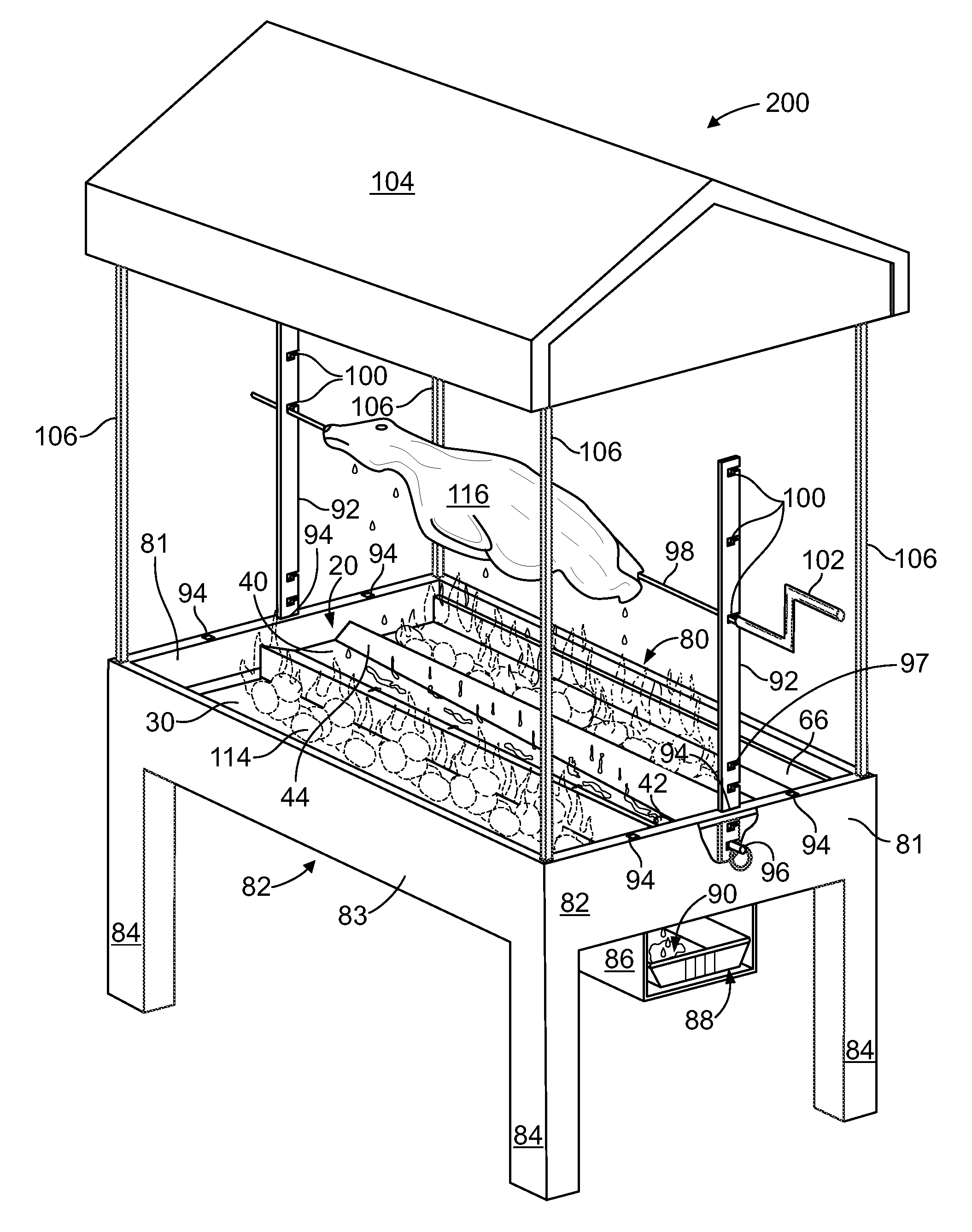
[0063]Unlike the hand crank 102 of the FIG. 11 embodiment 200, an electrically driven motor 108 is disposed at the proximal end of the rotisserie spit 98 and causes it to rotate at a desired speed. The motor 108 may be mounted through the rotisserie spit holes 210 and power for the operation of the motor may be available through motor power cable 110 connected to an electrical source such as a battery cell or an electrical outlet. Additional accessories, such as the wind block 112 mounted between the roof and the rectangular support structure 82, may be provided to block wind during device use. Fuel 114 is in the heat source beds 30, 52 and provides radiant heat to the meat or whole animal carcass 116. It is a known phenomenon that a continual wind directed toward the cooking meat significantly increases cooking time, so that wind block 112 reduces this effect.

[0064]FIG. 13 is a cross sectional view taken approximately along the lateral direction at the distal end of an alternative ...

embodiment 20

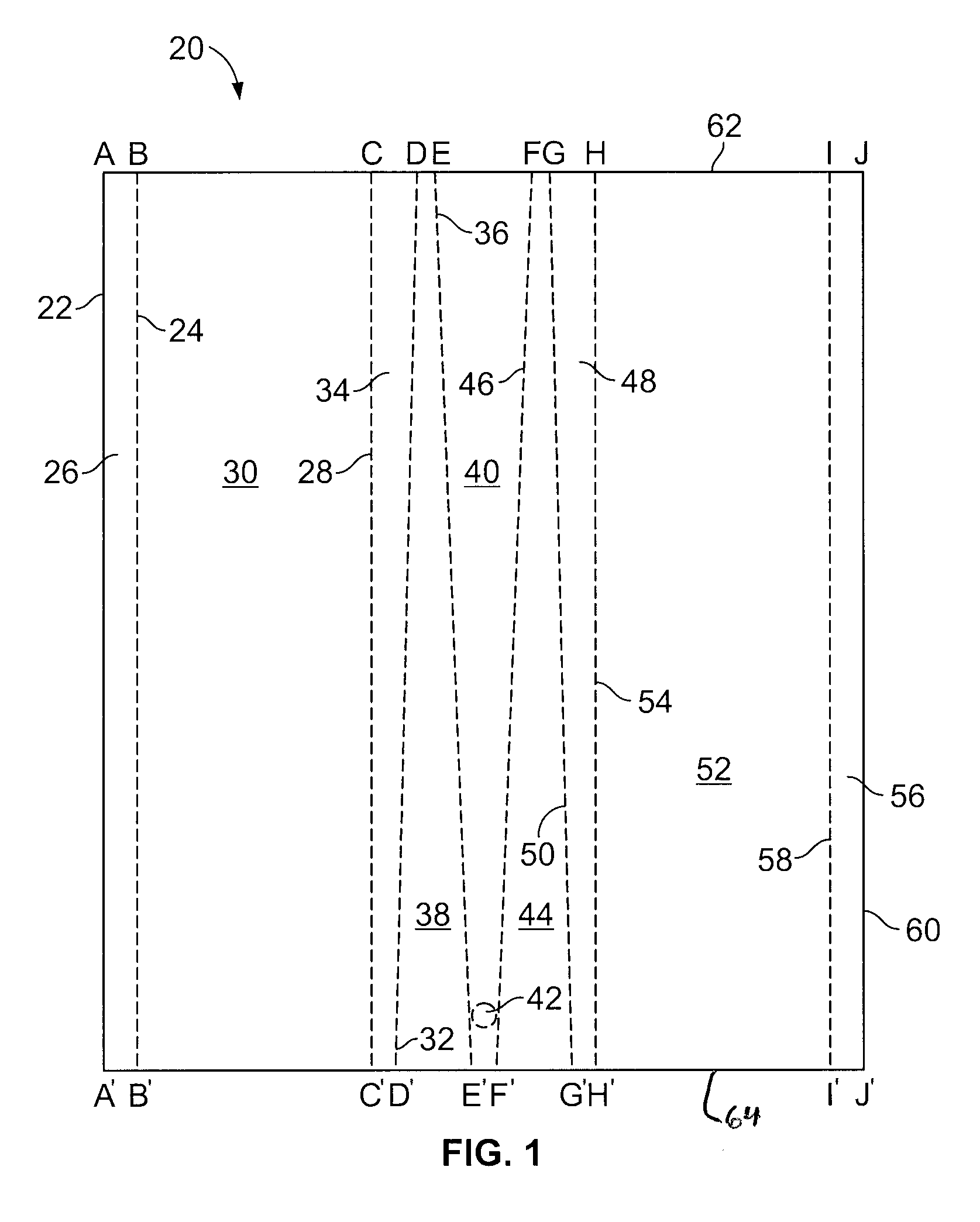
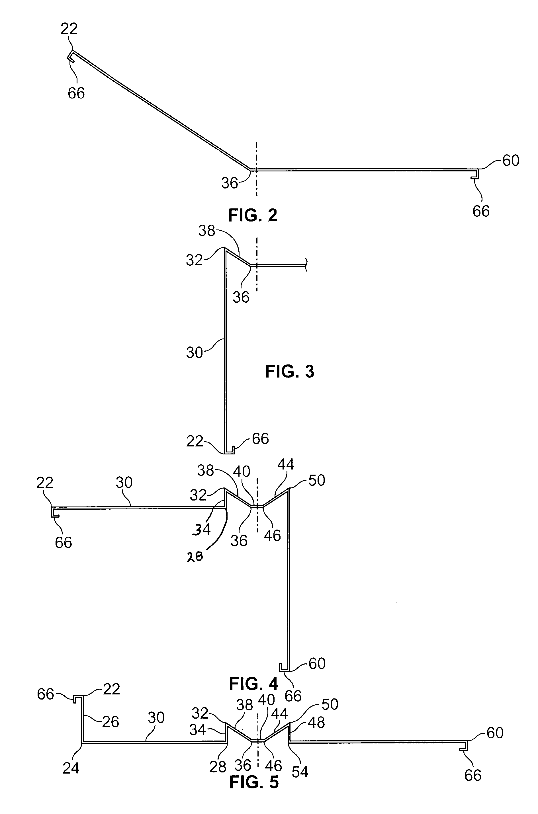
[0069]In the embodiment 20 shown in FIGS. 1 and 8-10, the lengths of segments AB=A′B′ and BC=B′C′ because even after the bends in the bending steps described above in reference to FIGS. 2-7, the bend lines 24, 28 and 54, 58 are all parallel to the longitudinal edges 22, 60 of the rectangular sheet 20. However, and because of the either converging or diverging nature of the bend lines 32, 36, 46 and 50 relative to the longitudinal edges 22, 60, the line segments CD, DE, EF, FG and GH do not equal the respective corresponding segments C′D′, D′E′, E′F′, F′G′ and G′H′. However, removing the segments that are equal to the corresponding ones on the other edge, the relationship of the remaining segments must add up to the same total length. That is, the length of segments CD+DE+EF+FG+GH=C′D′+D′E′+E′F′+F′G′+G′H′. Additionally, in order to obtain the desired slope in the channel surface 40 and, as compared in FIG. 1 and in FIGS. 8, 10, the discrete segments, should have the following relatio...


PUM

PropertyMeasurementUnit
Angleaaaaaaaaaa
Angleaaaaaaaaaa
Angleaaaaaaaaaa

Abstract

A unitary barbecue heat source bed and fluid removal channel combination, comprising a plurality of heat source beds, an inclined channel for removing fluid, the heat source beds being adjacent to the channel, wherein the heat source beds and channel are unitary and preferably made from a single sheet of metal.

Description

BACKGROUND OF THE INVENTION[0001]1. Field of the Invention[0002]This invention relates generally to rotisseries for cooking meat, and more particularly rotisserie grill used for cooking of a whole animal carcass adjacent a source of heat.[0003]2. Background Art[0004]Rotisserie barbecue grills involve roasting a whole animal carcass, usually over the heat source. During the roasting process, grease and fluids are released from the animal carcass. As these make contact with the heat source, the result is the heat source flame can flare-up and present a danger to those adjacent the rotisserie grill. Prior art attempts have been proposed that are directed to prevent flame flare-ups by the use of grease catching devices between the meat and the heat source.[0005]One prior art design disposes a grease dripping tray between the heat source and the animal carcass to collect grease drippings. These types of designs are not ideal because the tray is heated by the heat source from the heat sou...

Claims


Application Information

Patent Timeline
IPC IPC(8): A47J37/04A47J37/07B21D5/00
CPCA47J37/041A47J37/0786A47J37/0745A47J37/0704
Inventor CHRISTOPOULOS, JAMES
Owner CHRISTOPOULOS JAMES
Why Eureka
Try Eureka