

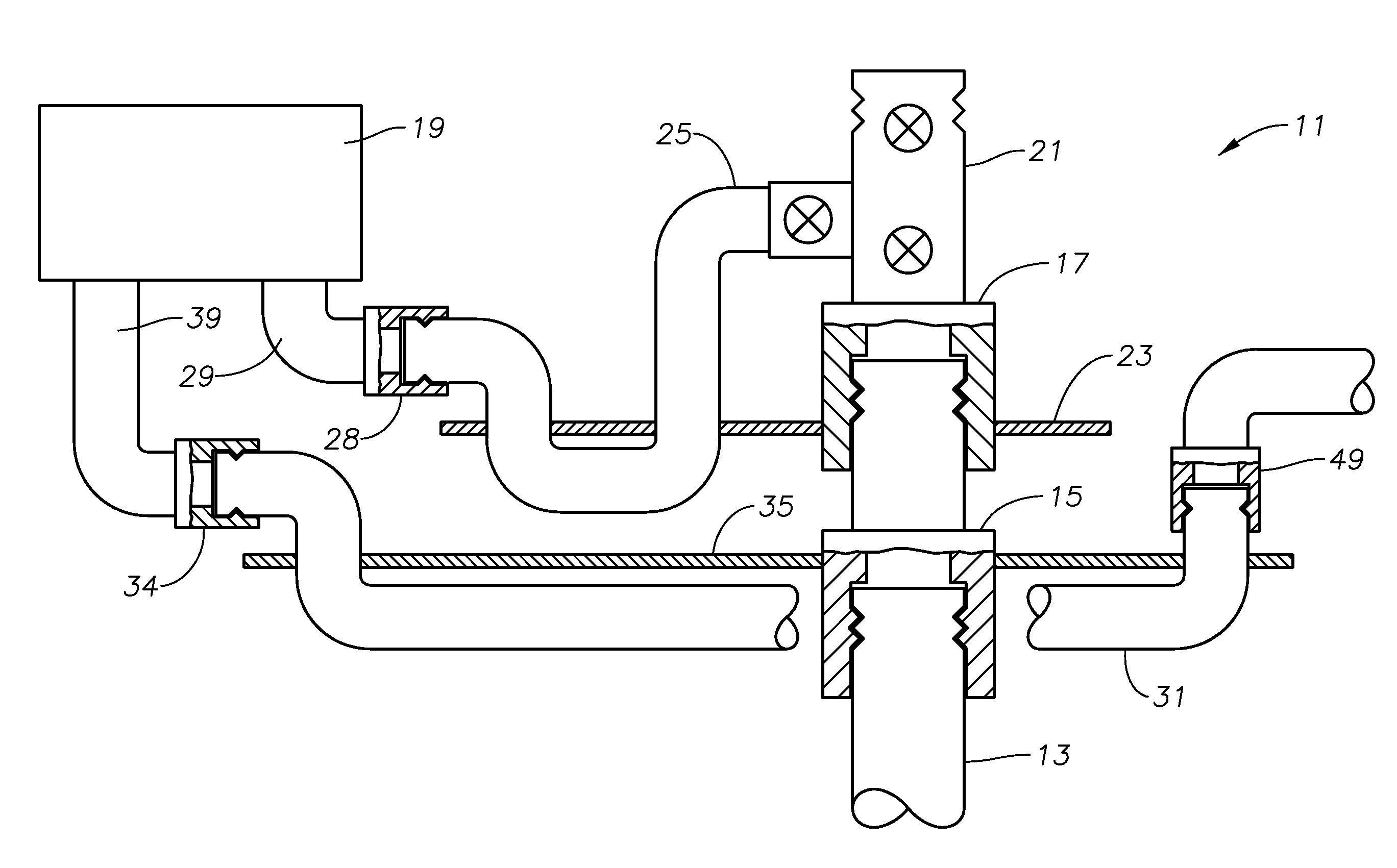
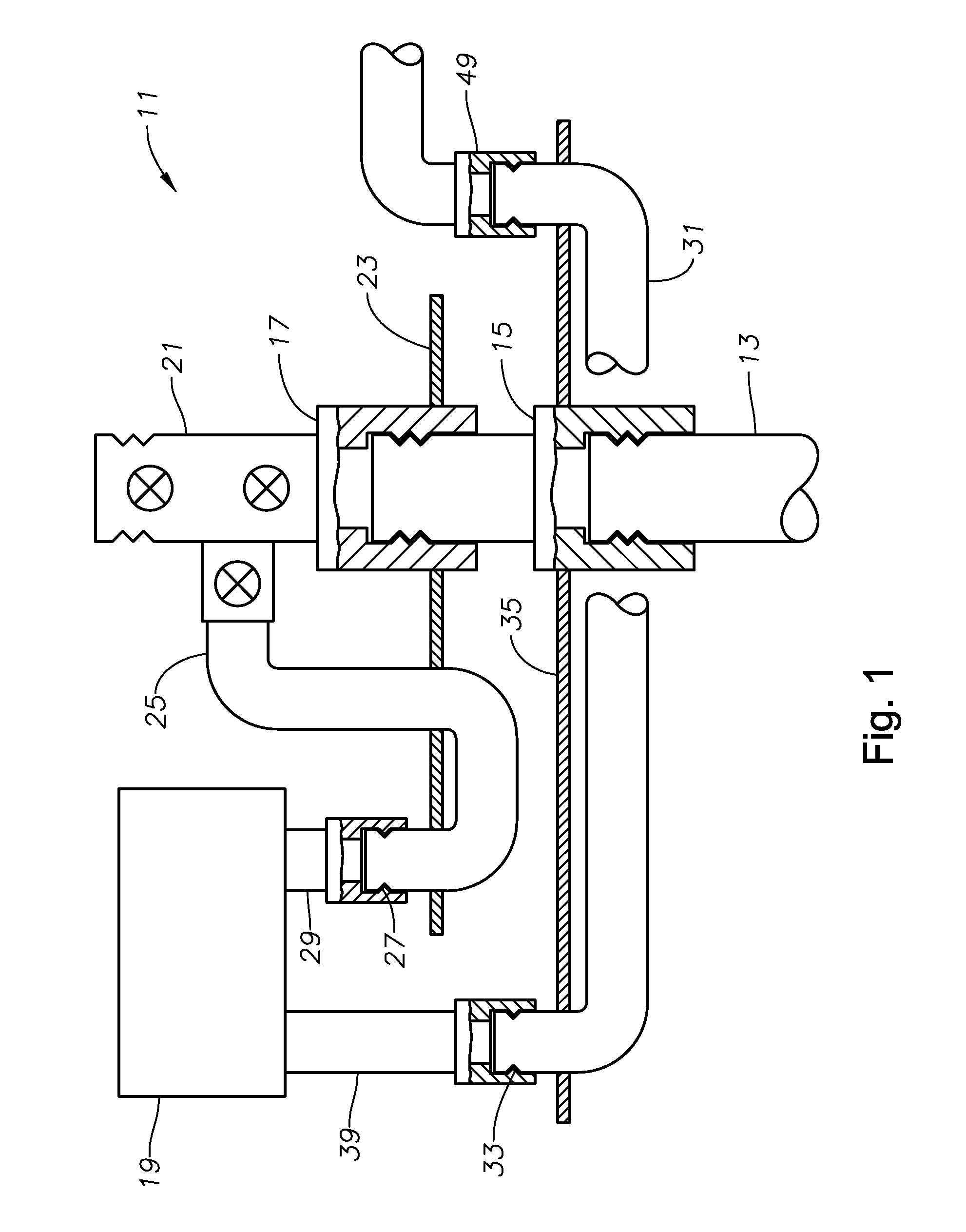
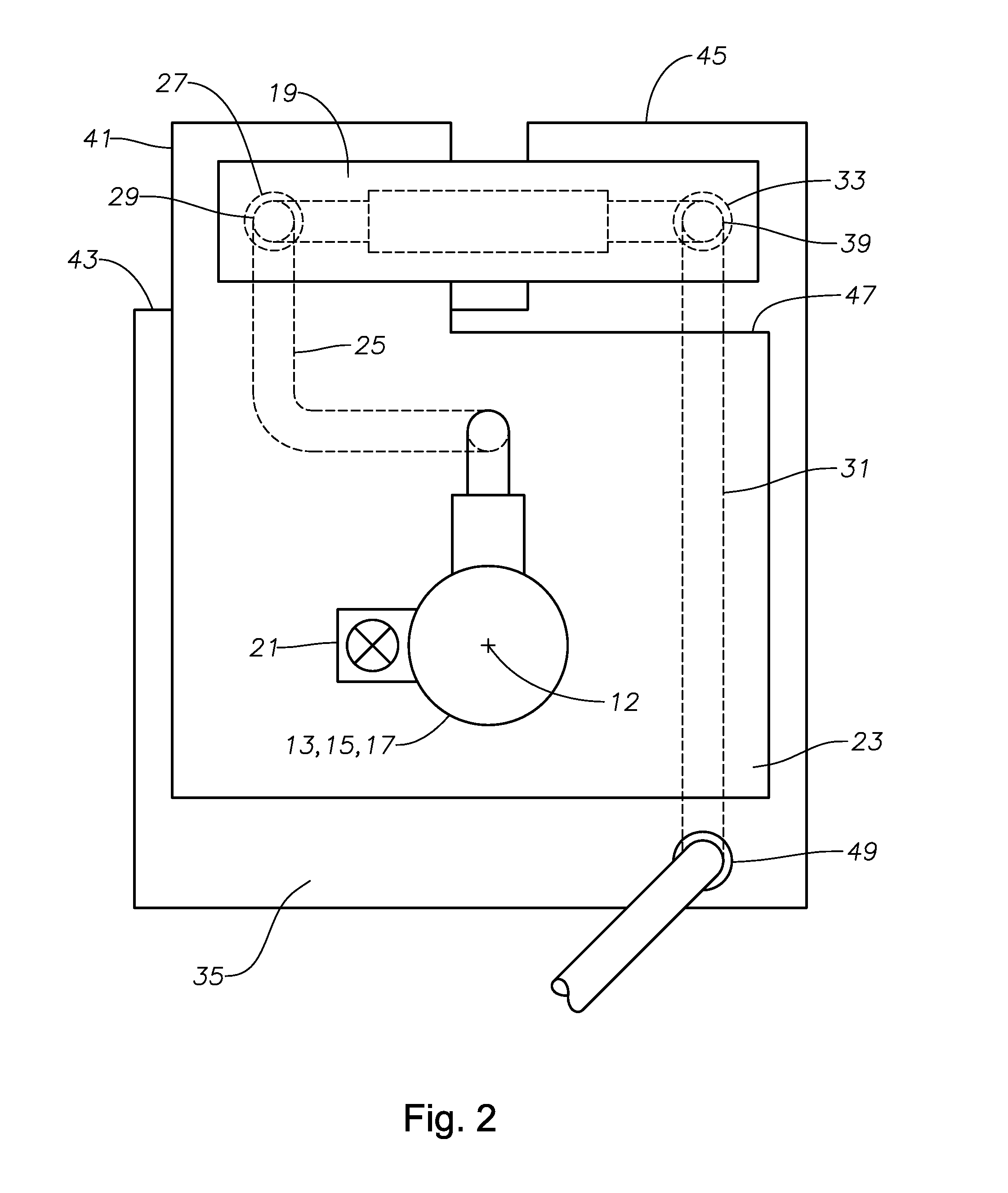
Flow module placement between a subsea tree and a tubing hanger spool
a technology of flow module and subsea tree, which is applied in the direction of underwater drilling, drilling machines and methods, and well accessories. it can solve the problems of significant pressure drop through the outboard flowline from the flow module, wear and fatigue at rates, and increase the heat loss of the well fluid into the surrounding environment. , to achieve the effect of shortening the flow path, reducing the amount of heat lost through the outboard flowline, and reducing the pressure drop across the system
- Summary
- Abstract
- Description
- Claims
- Application Information
AI Technical Summary
Benefits of technology
Problems solved by technology
Method used
Image

Examples
Embodiment Construction
[0018]The present invention will now be described more fully hereinafter with reference to the accompanying drawings which illustrate embodiments of the invention. This invention may, however, be embodied in many different forms and should not be construed as limited to the illustrated embodiments set forth herein. Rather, these embodiments are provided so that this disclosure will be thorough and complete, and will fully convey the scope of the invention to those skilled in the art. Like numbers refer to like elements throughout, and the prime notation, if used, indicates similar elements in alternative embodiments.
[0019]In the following discussion, numerous specific details are set forth to provide a thorough understanding of the present invention. However, it will be obvious to those skilled in the art that the present invention may be practiced without such specific details. Additionally, for the most part, details concerning rig operation, well drilling, downhole well completio...
PUM
 Abstract
Description
Claims
Application Information