Electrically-powered spreader

a technology of electric power and spreader, which is applied in the direction of application, way, and centrifugal wheel fertiliser, etc., can solve the problems of inefficiency of direct spreading of product using the user's hands, inability to execute, and difficulty in accurately controlling the area to which the product is applied

Inactive Publication Date: 2013-01-03
LEBANON SEABOARD CORP
View PDF7 Cites 12 Cited by
  • Summary
  • Abstract
  • Description
  • Claims
  • Application Information

AI Technical Summary

Problems solved by technology

Spreading product directly using the user's hands is inefficient, nearly impossible to execute in a manner that results in even spreading of the product, and can be dangerous if the product is of the type not intended for sustained contact with human skin.
Broadcast spreaders are generally useful only for very large treatment areas, as it can be difficult to accurately control the area to which the product is applied.
Furthermore, the broadcast spreader is relatively expensive and there is substantial overhead in setting the spreader up, filling and refilling the hopper, and then storing the spreader when not in use.
Product that is supplied in bottles and shaken out of the spout offers the convenience of contained product and low overhead, but the act of shaking the product out of the bottle can very quickly cause fatigue to the user's hand and arm muscles.

Method used


Image

  • Electrically-powered spreader
  • Electrically-powered spreader
  • Electrically-powered spreader

Examples


first embodiment

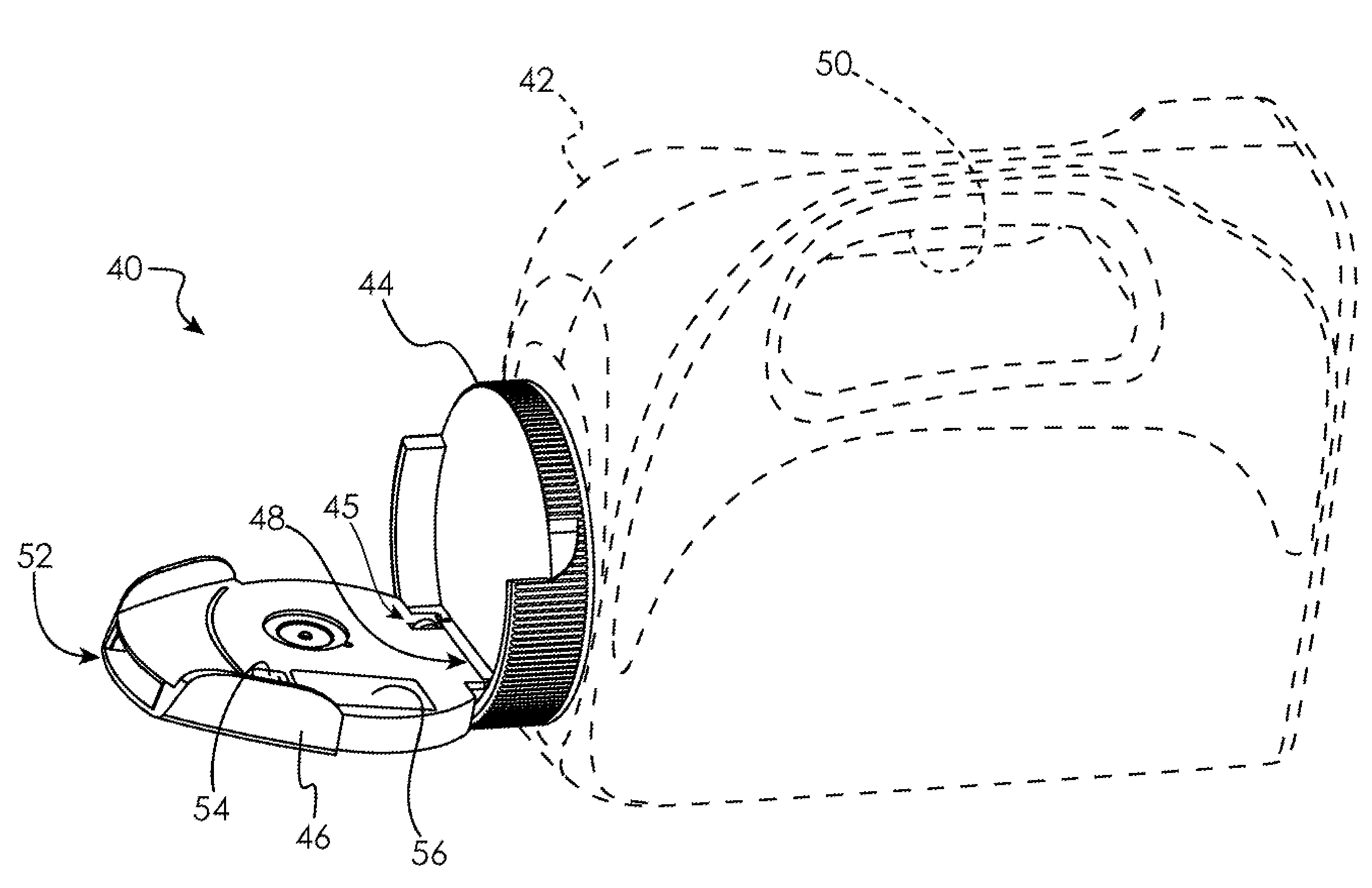
[0027]A first embodiment cap is illustrated in FIG. 4, and indicated generally at 40. Cap 40 fits onto a bottle 42 of any desired configuration in order to close an opening in said bottle 42. Although a plastic bottle 42 having a particular shape and configuration is illustrated in the drawings, those skilled in the art will appreciate that the presently disclosed embodiments will find application with bottles of varying designs, and manufactured from various materials, and the present invention is intended to encompass bottles of any configuration. Cap 40 is shown in the closed position in FIG. 4, where cap 40 prevents the granular content of the bottle 42 from escaping the bottle's opening (under cap 40, not shown). Cap 40 is shown in the open position in FIG. 5.

[0028]Cap 40 includes a base portion 44 that attaches to the bottle 42 and covers at least the opening in the bottle 42. Cap 40 may attach to bottle 42 by any removable or non-removable means, including ultrasonic welding,...

second embodiment

[0039]FIG. 9 illustrates a second embodiment impeller assembly comprising a blade 90 that pivots upon a shaft 92. The blade 90 is made to alternately pivot around the shaft 92 in a counter-clockwise direction and a clockwise direction, similar in fashion to a wiper blade on an automobile windshield. The blade 90 pivots from the point 94 to the point 96 before returning to the point 94 to begin the cycle once again. In this manner, the impeller blade 90 continuously sweeps granular product that is entering the cavity 80 at opening 62 toward the opening 52.

[0040]FIG. 10 illustrates a third embodiment impeller assembly comprising a continuous track 100 riding upon wheels 102 and 104. Mounted at intervals upon the track 100 are impeller vanes 106. It will be noted that in the third embodiment the cavity 80 is not circularly shaped, but rather elongated. The wheel 104 is made to rotate by a convenient means, such as by motor 107, thereby rotating the track 100 and the impeller vanes 106....


PUM


Abstract

An electrically-powered spreader for spreading a granular product is disclosed. The spreader may comprise a cap used to close a bottle containing the granular product. When in the open position, the bottle may be tilted into a position in which the granular product is fed by the force of gravity through an opening and into the spreader cap. A moving member within the spreader cap interacts with the granular product to propel it out of an opening in the spreader cap. In this way, the granular product is broadcast out of the bottle and onto the treatment area around the bottle.

Description

TECHNICAL FIELD OF THE INVENTION[0001]The present disclosure generally relates to material handling and, more particularly, to an electrically-powered spreader for granular product.BACKGROUND OF THE INVENTION[0002]In the field of horticulture, it is commonplace to spread granular adjuncts over surfaces to be treated. For example, grass seeds may be spread over lawns to initiate growth of grass in the treated area. Also, granular fertilizers may be spread in order to provide additional nutrients to the treated area. Likewise, granular pre-emergent herbicides may be spread over a planting area to prevent the germination of weed seeds in areas where desirable plants are already growing.[0003]There are multiple methods known in the art for dispersing granular products onto treatment areas. In the simplest form, the product may be scooped into the user's hand and tossed over the treatment area. For larger treatment areas, it has been found useful to employ a device known as a broadcast s...

Claims


Application Information

Patent Timeline
Patent Type & Authority Applications(United States)
IPC IPC(8): A01C17/00B65G31/04A01C7/16
CPCA01C15/02A01C7/02
Inventor MARCONI, JR., FRED A.
Owner LEBANON SEABOARD CORP
Why Eureka
Try Eureka