Heat fixing device

a technology of fixing device and heat, which is applied in the direction of instruments, electrographic process equipment, optics, etc., can solve the problems of excessive temperature in the region through which the recording material does not pass in the heat fixing device, deterioration of fixability, and excessive elevation of temperature in the region through which the recording material does not pass, so as to reduce the waste of electric power and reduce the effect of temperature elevation

Active Publication Date: 2013-01-10
CANON KK
View PDF12 Cites 19 Cited by
  • Summary
  • Abstract
  • Description
  • Claims
  • Application Information

AI Technical Summary

Benefits of technology

[0008]An aspect of the present invention is directed to a heat fixing device with reduced waste of electric power, which can strike a good balance between reduction of temperature elevation in a paper non-passing region and acquisition of fixability.

Problems solved by technology

When a toner image is printed on a small-sized recording material, temperature in a region through which the recording material does not pass in the heat fixing device is excessively elevated.
However, this method has a problem in that some wind sent from the cooling fan to the paper non-passing region to be elevated in temperature in the heating member enters the inside of a paper passing region to drop the temperature in edges of the paper passing region in the heating member (temperature drop).
However, since the air volume is large, some of the wind also lowers the temperature in the edges of the paper passing region in the heating member.
This deteriorates a fixability and causes an uneven gloss in both edges of the small sized recording material.
Thus, to maintain the fixability, the air volume in the cooling fan cannot be increased simply.
However, in Japanese Patent Application Laid-Open No. 2009-288275, the heat volume in the region to be cooled is increased, and thus, wasted electricity is consumed.
To deal with this excessive temperature elevation, a cooling fan with high power is required, easily leading to increasing in size of the apparatus.

Method used


Image

  • Heat fixing device
  • Heat fixing device
  • Heat fixing device

Examples


Embodiment Construction

[0023]Various exemplary embodiments, features, and aspects of the invention will be described in detail below with reference to the drawings.

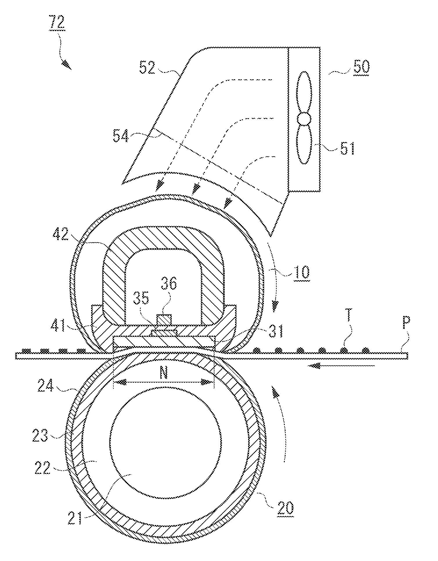
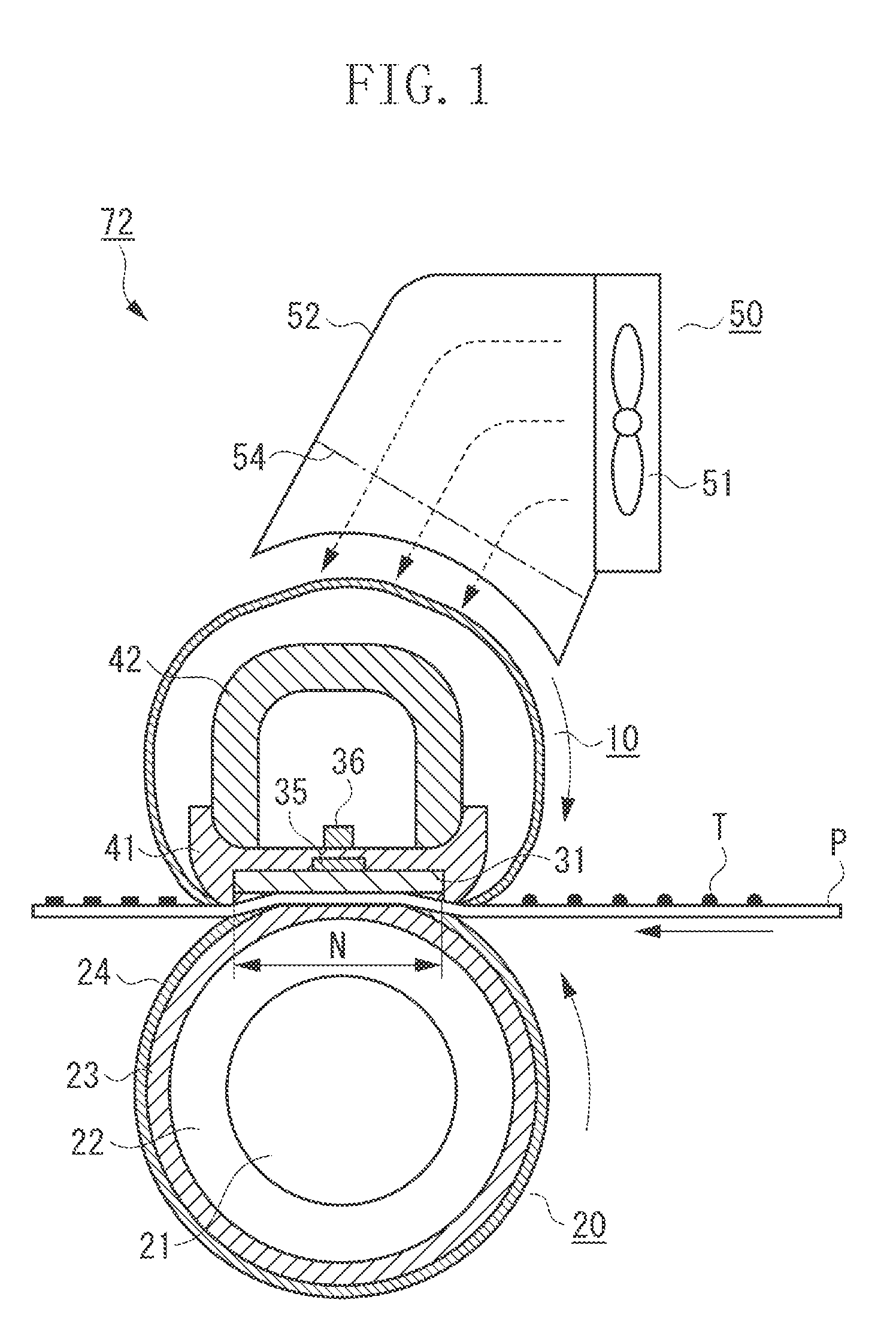
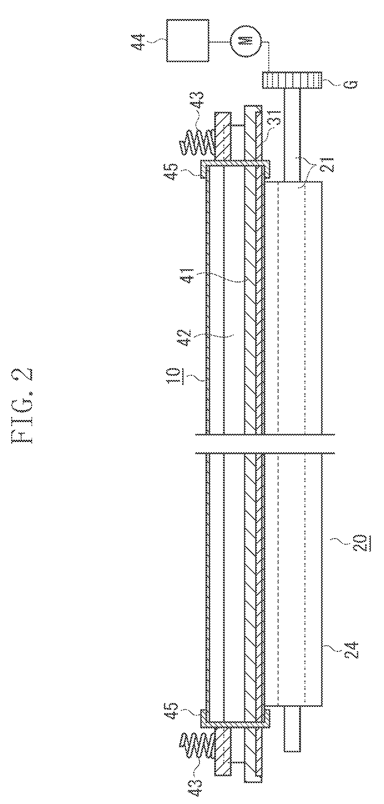
[0024]In the following description, concerning a heat fixing device and members that compose the heat fixing device, a lengthwise direction is a direction orthogonal to a recording material conveying direction (axis direction of pressing roller) on a surface of a recording material. The lengthwise direction is also a direction orthogonal to a rotation direction of a rotatable member for heating described below. A crosswise direction is a direction parallel with the recording material conveying direction on the surface of the recording material. An axis direction concerning the recording material is a direction orthogonal to the recording material conveying direction on the surface of the recording material.

[0025]FIG. 1 is a cross-sectional view of a heat fixing device 72 that fixes an unfixed toner image formed on the recording material onto th...


PUM


Abstract

A heat fixing device includes a rotatable member for heating, a pressing roller configured to form a fixing nip portion that nips and conveys a recording material bearing a toner image, and a cooling fan configured to cool a recording material non-passing region in the rotatable member for heating in a direction orthogonal to a recording material conveying direction, wherein the pressing roller includes a rubber layer, between a cored bar and a release layer, containing a needle-shaped heat conductive filler oriented in a roller axis direction.

Description

BACKGROUND OF THE INVENTION[0001]1. Field of the Invention[0002]The present invention relates to a heat fixing device equipped on an image forming apparatus such as an electrophotographic copying machine and an electrophotographic printer.[0003]2. Description of the Related Art[0004]An image forming apparatus such as a copying machine and a printer of an electrophotographic system is equipped with a heat fixing device that fixes a toner image on a recording material. When a toner image is printed on a small-sized recording material, temperature in a region through which the recording material does not pass in the heat fixing device is excessively elevated. As one measure for the temperature to be excessively elevated, a technique in which a cooling fan that cools a paper non-passing region is provided is available.[0005]In Japanese Patent Application Laid-Open No. 2007-187816, a cooling unit (a cooling fan) that cools the paper non-passing region of a heating member is provided to r...

Claims


Application Information

Patent Timeline
Patent Type & Authority Applications(United States)
IPC IPC(8): G03G21/20
CPCG03G15/206G03G15/2017
Inventor KAINO, TOSHIYAIZAWA, SATORUNIHONYANAGI, KOJIKASUGA, KUNIAKIMINAGAWA, TAISUKENEGISHI, HAYATOASAMI, JUN
Owner CANON KK
Why Eureka
Try Eureka