
Developer Container and Image Forming Apparatus Including The Same

a technology of developing container and image forming apparatus, which is applied in the direction of electrographic process apparatus, instruments, optics, etc., can solve the problems of complex structure of developing unit, and so as to prevent defective image formation, suppress uneven level of developer, and prevent defective image formation

Active Publication Date: 2013-01-10
BROTHER KOGYO KK
View PDF2 Cites 8 Cited by
  • Summary
  • Abstract
  • Description
  • Claims
  • Application Information

AI Technical Summary

Benefits of technology

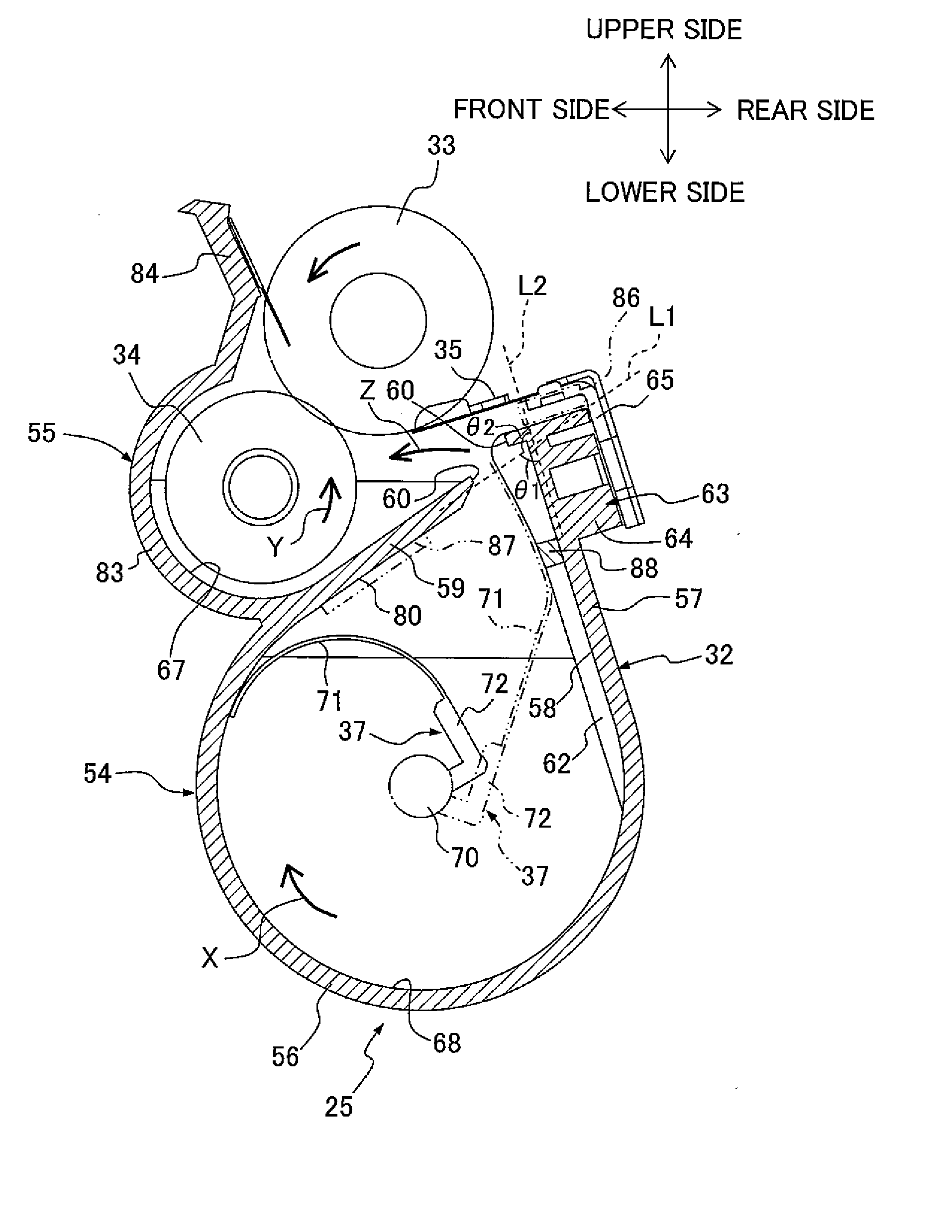
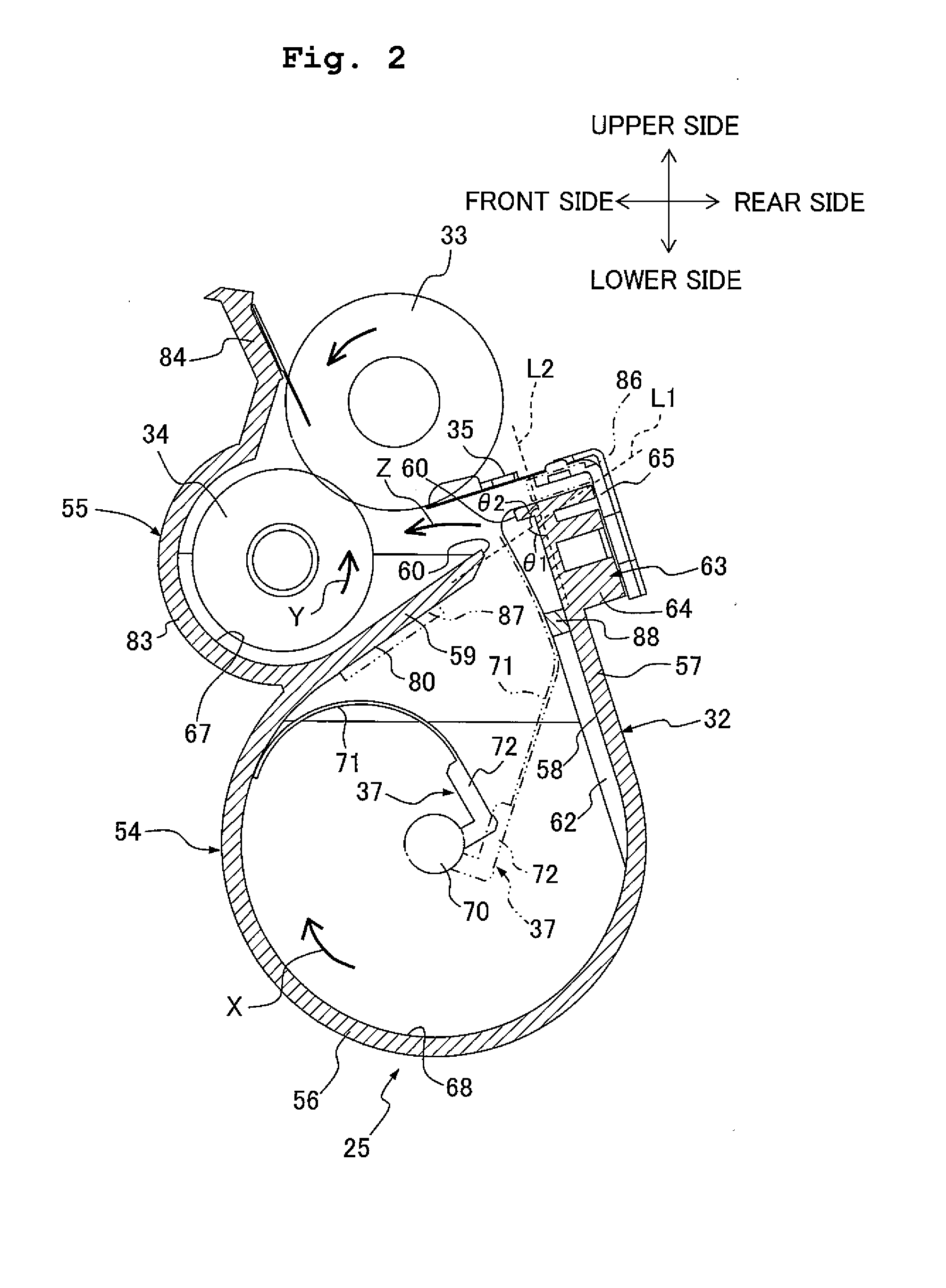
The present invention provides a developer container and an image forming apparatus equipped with the developer container that can prevent defective image formation caused by uneven developer levels. This is achieved by using an air flow generated by the collision of a transporting member with a contacting portion to supply developer from the contacting portion to the outside of the developer accommodating chamber, leading to a more uniform level of developer supplied to the outside of the chamber. This results in a reduction of the uneven developer level and prevents defective image formation. The developer container and image forming apparatus according to the present invention can facilitate small-sizing and cost reduction while preventing defective image formation.

Problems solved by technology

Therefore, there is a fear that the developer is not supplied evenly to the developing chamber, which may give rise to an uneven level of developer.
Moreover, due to such uneven level of developer, the developer may not be supplied uniformly to the supply roller, and furthermore, the developer may not be carried uniformly on the developing roller, which may lead to a defective image formation.
However, when the stirring member is provided in the developing chamber, the structure of the developing unit becomes complicated, and facilitating small-sizing and cost-reduction of the developing unit becomes difficult.

Method used


Image

  • Developer Container and Image Forming Apparatus Including The Same
  • Developer Container and Image Forming Apparatus Including The Same
  • Developer Container and Image Forming Apparatus Including The Same

Examples


Embodiment Construction

A. Overall Structure of Color Printer

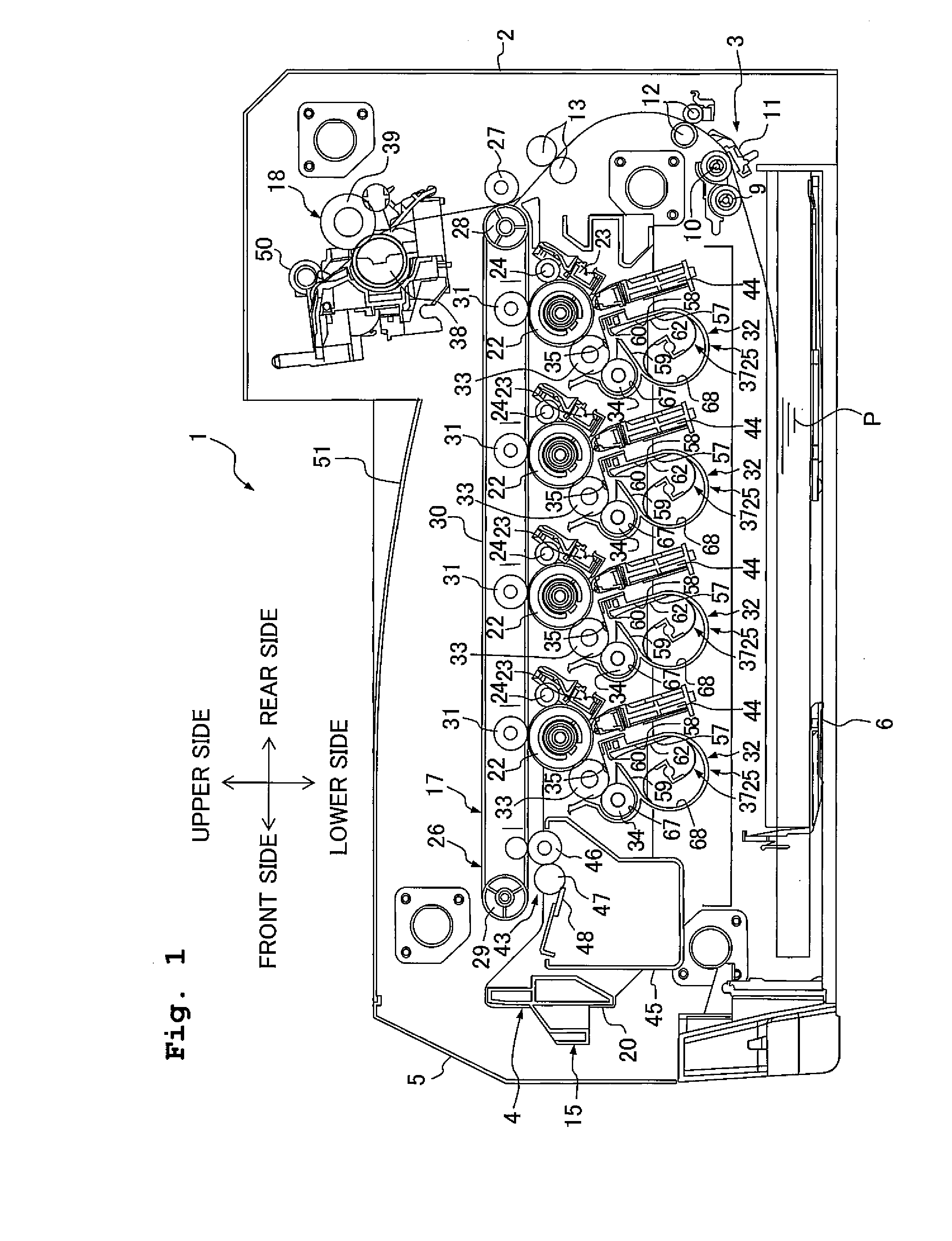
[0041]As shown in FIG. 1, a color printer 1 as an example of an image forming apparatus is an intermediate transfer type color printer of a horizontally-mounted type.

[0042]Moreover, the color printer 1 includes a main-body casing 2, and a paper feeding section 3 for feeding a paper P, and an image forming section 4 for forming an image on the supplied paper P. The paper feeding section 3 and the image forming section 4 are accommodated in the casing 2.

[0043]The main-body casing 2 is formed to be box-shaped in a substantially rectangular form in a side view, and is configured to accommodate the paper feeding section 3 and the image forming section 4. A front cover 5 is swingably or pivotably provided on one side wall of the main-body casing 2. A lower-end portion of the front cover 5 is fixed on the one side wall as a supporting point of a pivot.

[0044]In the following description, a side at which the front cover 5 is provided is defined as a front...


PUM


Abstract

A developer container includes a developer accommodating chamber and a transporting member configured to elastically deform, to rotate, and to transport the developer accommodated in the developer accommodating chamber. The developer accommodating chamber includes a dividing wall configured to deform the transporting member by making a sliding contact with the transporting member. The developer accommodating chamber further includes a communicating portion configured to allow the transporting member, which has been elastically deformed by the sliding portion, to restore. The developer accommodating chamber still further includes a contacting portion. The transporting member restored by the communicating portion being configured to contact with the contacting portion.

Description

CROSS REFERENCE TO RELATED APPLICATION[0001]The present application claims priority from Japanese Patent Application Nos. 2011-151771 and 2012-137523, filed on Jul. 8, 2011, and Jun. 19, 2012, respectively, the disclosures of which are incorporated herein by reference in their entirety.BACKGROUND OF THE INVENTION[0002]1. Field of the Invention[0003]The present invention relates to an image forming apparatus in which an electrophotography is adopted, and a developer container which is equipped in the image forming apparatus.[0004]2. Description of the Related Art[0005]As an electrophotographic color printer, an intermediate-transfer type color printer which includes a plurality of developing units, a plurality of photosensitive drums which are disposed in parallel above the developing units corresponding to the respective developing units, an endless belt which makes a contact with each photosensitive drum from an upper side thereof, and a secondary transfer roller which makes a cont...

Claims


Application Information

Patent Timeline
Patent Type & Authority Applications(United States)
IPC IPC(8): G03G15/08
CPCG03G15/0877G03G15/0865
Inventor SENDA, SEIICHIYOSHIKAWA, MASANARI
Owner BROTHER KOGYO KK
Learn More