
Exhaust diagnostic system and method with scr nh3 depletion cleansing mode for initial step in the def quality service healing test

a diagnostic system and exhaust system technology, applied in the direction of machines/engines, electrical control, instruments, etc., can solve the problems of low nox reduction efficiency, inability to detect an unacceptable level of scr performance, and inability to reduce the quality of scr components

Active Publication Date: 2013-01-17
GM GLOBAL TECH OPERATIONS LLC
View PDF10 Cites 11 Cited by
  • Summary
  • Abstract
  • Description
  • Claims
  • Application Information

AI Technical Summary

Benefits of technology

The patent describes an exhaust diagnostic system that includes a module for testing the efficiency of a selective catalyst reduction (SCR) component. This system also has a module for managing the temperature of the SCR component to a specific range, and another module for depleting the reductant load and initiating an SCR component efficiency test if the previous test fails while the temperature of the SCR component is within the predetermined range. The technical effect of this invention is to provide a more accurate and efficient method for diagnosing the performance of SCR components in exhaust systems, which can help to improve the overall efficiency and performance of the exhaust system.

Problems solved by technology

Exhaust systems with SCR components may be vulnerable to poor quality reductant.
If a reductant tank has been filled with poor quality reductant, an exhaust diagnostic system may detect an unacceptable level of performance for the SCR component, such as a low NOx reduction efficiency.
For example, if acceptable reductant is not added soon after detection of a low SCR conversion efficiency, some controls may limit vehicle speed, e.g., to 55 mph and ultimately to 4 mph, in accordance with government requirements.
During speed limitation, however, the temperature range of the exhaust stream may be, for example only, less than 250 degrees C. Thus, after a vehicle has been speed limited and / or other remedial action has been taken, the remedial measures may prevent sufficient heat from being generated in the exhaust stream to accurately evaluate the SCR conversion efficiency.
In this way, the imposition of remedial measures may interfere with the ability to verify whether the reductant has been replaced.
Unfortunately, without an evaluation of the SCR conversion efficiency, no acceptable method currently exists to reset the exhaust diagnostic system after the speed of the vehicle has been limited following detection of poor reductant quality and / or low SCR conversion efficiency.
This solution is unfavorable, however, due to the ready availability of scan tools to the general public, enabling some vehicle operators to inappropriately reset the exhaust diagnostic system to circumvent the purpose behind the measures and thereby enable use of ineffective reductants such as water.
As a result, in some cases, no mechanism is provided for resetting the system via a scan tool.
Moreover, many customers lack access to a scan tool.
Nonetheless, even where reductant quality can reliably be determined, when a vehicle has encountered a NOx efficiency issue, the model employed by the control to track and / or predict how much reductant is loaded in the SCR component may be susceptible to inaccuracies.

Method used


Image

  • Exhaust diagnostic system and method with scr nh3 depletion cleansing mode for initial step in the def quality service healing test
  • Exhaust diagnostic system and method with scr nh3 depletion cleansing mode for initial step in the def quality service healing test
  • Exhaust diagnostic system and method with scr nh3 depletion cleansing mode for initial step in the def quality service healing test

Examples


Embodiment Construction

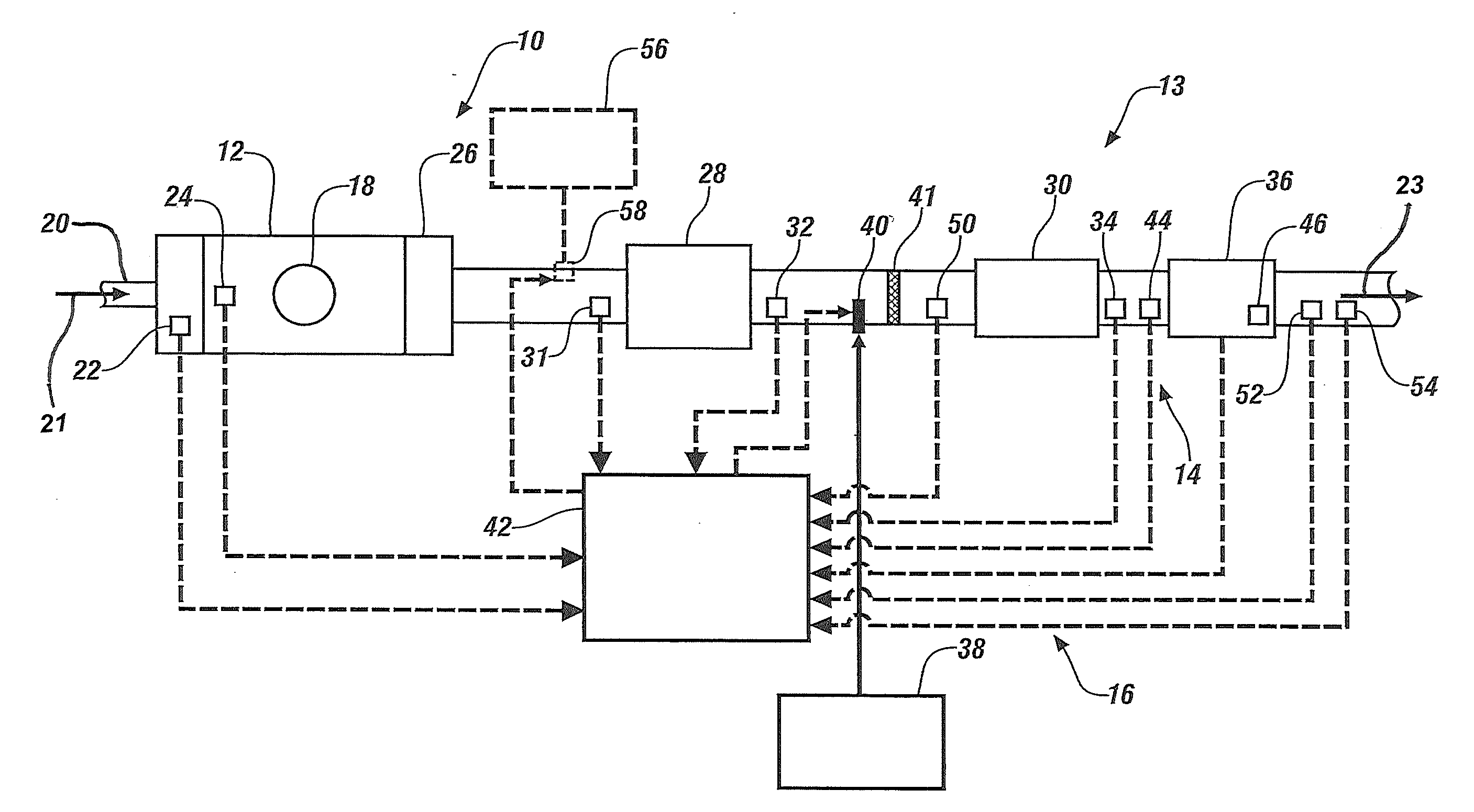
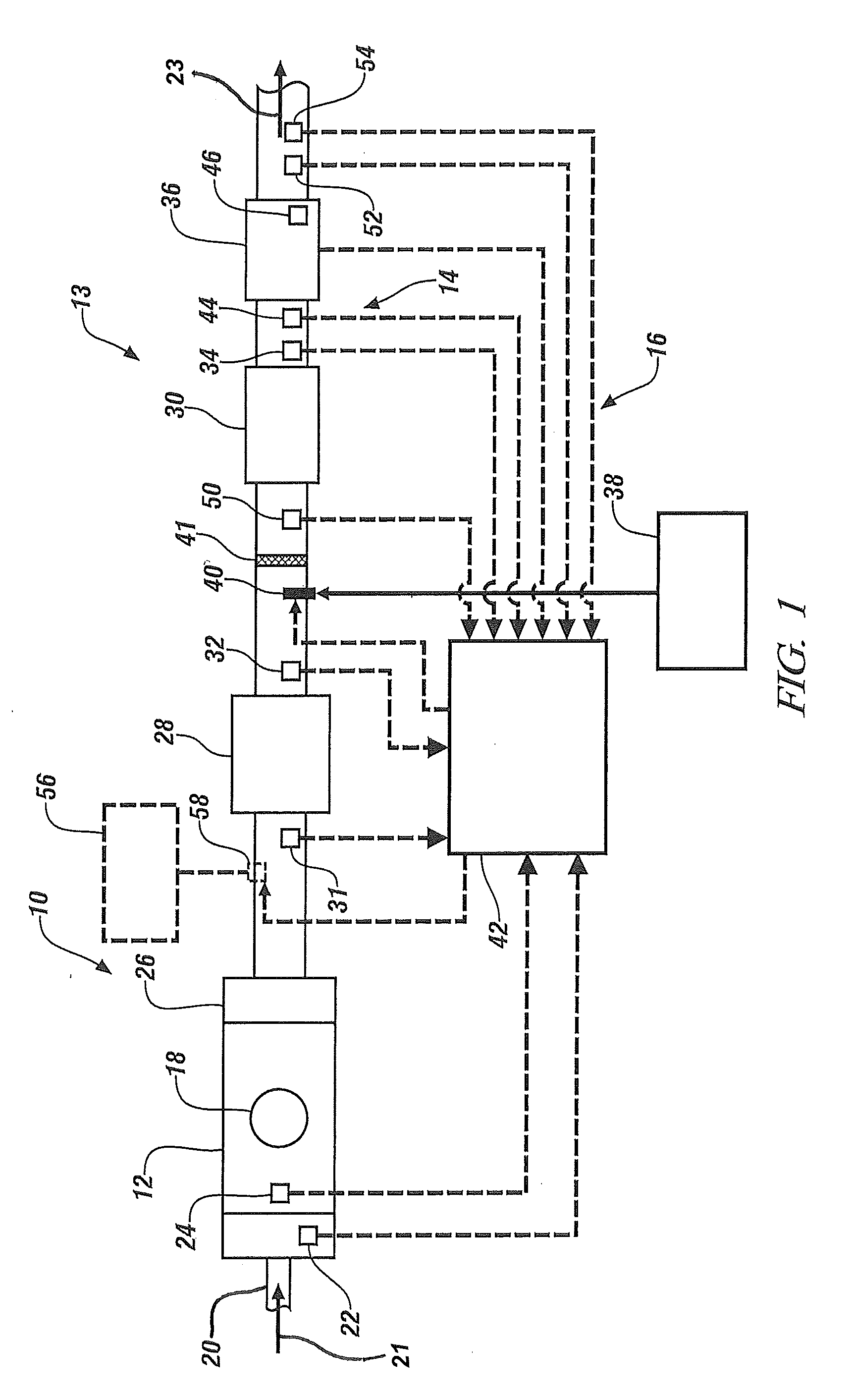
[0019]The following description is merely exemplary in nature and is in no way intended to limit the disclosure, its application, or uses. For purposes of clarity, the same reference numbers will be used in the drawings to identify similar elements. As used herein, the phrase at least one of A, B, and C should be construed to mean a logical (A or B or C), using a non-exclusive logical or. It should be understood that steps within a method may be executed in different order without altering the principles of the present disclosure.

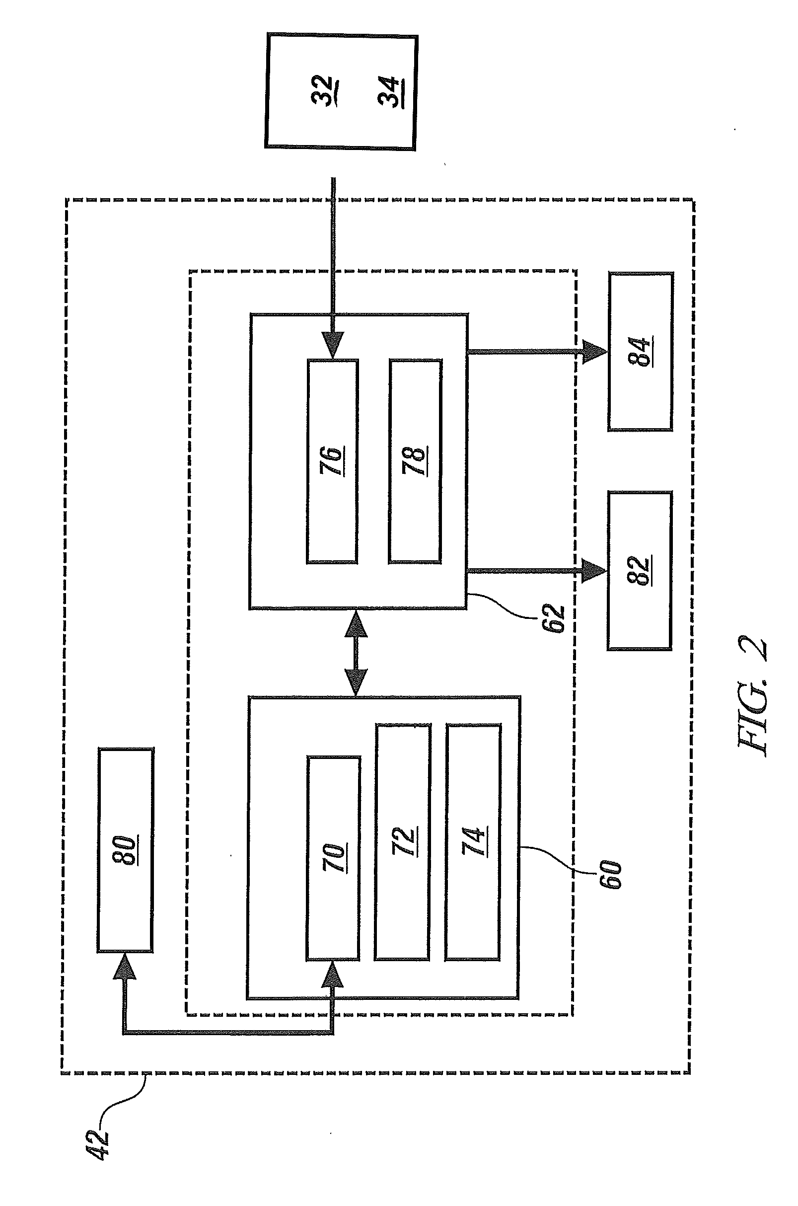
[0020]As used herein, the term “module” refers to an Application Specific Integrated Circuit (ASIC), an electronic circuit, a processor (shared, dedicated, or group) and memory that execute one or more software or firmware programs, a combinational logic circuit, and / or other suitable components that provide the described functionality.

[0021]While the following disclosure involves diesel engines, other types of engines such as gasoline engines, including di...


PUM


Abstract

An exhaust diagnostic system comprises a selective catalyst reduction (SCR) component testing module, an exhaust stream temperature management module, and a test enabling module. The component testing module executes an SCR component efficiency test. The exhaust stream temperature management module adjusts a temperature of the SCR component to a predetermined temperature range. The test enabling module executes a process for depleting a reductant load and subsequently initiates an SCR component efficiency test while the temperature of the SCR catalyst is within the predetermined temperature range.A method for diagnosing an exhaust system comprises determining an efficiency of an SCR component and selectively adjusting a temperature of the SCR component to a predetermined temperature range. The method also includes executing a process for depleting a reductant load and initiating an SCR component efficiency test while the temperature of the SCR component is within the predetermined temperature range.

Description

CROSS-REFERENCE TO RELATED APPLICATION[0001]The present patent application claims the benefit of priority from U.S. provisional patent application No. 61 / 507,195 filed on Jul. 13, 2011, which is incorporated herein by reference in its entiretyFIELD OF THE INVENTION[0002]The subject invention relates to vehicle exhaust systems, and more particularly to exhaust diagnostic systems and methods that evaluate performance of selective catalyst reduction (SCR) components and processes.BACKGROUND[0003]The background description provided herein is for the purpose of generally presenting the context of the disclosure. Work of the presently named inventors, to the extent it is described in this background section, as well as aspects of the description that may not otherwise qualify as prior art at the time of filing, are neither expressly nor impliedly admitted as prior art against the present disclosure.[0004]During combustion in a diesel engine, an air / fuel mixture is delivered through an int...

Claims


Application Information

Patent Timeline
IPC IPC(8): G01M15/04
CPCF01N3/106F01N13/009F02D41/0235F01N11/002F01N3/035F01N2550/02F01N2560/06F01N2560/14F01N2900/1602F02D41/1446F02D41/1463F02D2200/0802Y02T10/47Y02T10/24F01N3/208Y02A50/20Y02T10/12Y02T10/40
Inventor LEVIJOKI, STEPHEN PAULTHOMPSON, BRETT B.SHETNEY, JUSTIN A.JASINKIEWICZ, PAUL
Owner GM GLOBAL TECH OPERATIONS LLC
Learn More