Liquid ejection head and liquid ejection device

a liquid ejection and liquid ejection technology, applied in the direction of printing, inking apparatus, etc., can solve the problems of high positioning accuracy and non-generation of kind of problems

Inactive Publication Date: 2013-01-17
SEIKO EPSON CORP
View PDF2 Cites 8 Cited by
  • Summary
  • Abstract
  • Description
  • Claims
  • Application Information

AI Technical Summary

Benefits of technology

[0008]An advantage of some aspects of the invention is to provide a liquid ejection head and a liquid ejection device which may obtain higher arrangement density of nozzle openings and easily position a nozzle plate and individual flow paths to thereby suppress trouble such as defective ejection of a liquid, and the like.
[0010]According to the aspect of the invention, by making a width of the communicating portion in the first direction greater than that of the pressure generating chamber, a high accuracy in positioning between the communicating portion and the nozzle openings may not be required, thereby easily performing the positioning. As a result, it is possible to suppress defective ejection of a liquid due to displacement between the communicating portion and the nozzle openings. In addition, by arranging the communicating portion of the second individual flow path row between the pressure generating chambers of the first individual flow path row, an interval between the pressure generating chambers adjacent to each other in the first direction may be reduced, thereby increasing arrangement density of the nozzle openings communicating with the pressure generating chamber in the first direction.
[0011]Here, it is preferable that a width of the pressure generating chamber in the first direction become narrowed on a side communicating with the communicating portion, and the communicating portion of the second individual flow path row be provided between communicating sides with the communicating portion of the pressure generating chambers of the first individual flow path row. Due to this, by arranging the communicating portion of the second individual flow path row between portions in which the width of the pressure generating chamber of the first individual flow path row becomes narrower, an interval between the pressure generating chambers adjacent to each other in the first direction may be further reduced, thereby increasing arrangement density of the nozzle openings communicating with the pressure generating chamber in the first direction.
[0012]In addition, it is preferable that a distance from the pressure generating chamber to the nozzle openings be provided with the same length on each of the individual flow paths. Due to this, it is possible to suppress occurrence of variations in ejection characteristics of liquid droplets ejected from each of the nozzle openings, in particular, an ejection velocity or an ejection weight.
[0013]In addition, it is preferable that the communicating portion and the nozzle openings be communicated with each other through a nozzle communicating hole provided so as to penetrate in a laminated direction between the nozzle plate and the flow path member. Due to this, a width of the communicating hole in the first direction may be increased by matching the communicating portion having a wide width, so that a high accuracy in positioning between the communicating hole and the nozzle openings may not be required, thereby easily performing the positioning.
[0015]According to the aspect of the invention, impacting position to a medium to be ejected with a liquid may be provided at a high density, and positioning between the nozzle plate and the individual flow paths may be easily performed, thereby realizing a liquid ejection device that prevents trouble such as defective ejection of a liquid, and the like.

Problems solved by technology

However, when the nozzle openings are provided in the zigzag arrangement, it is necessary that a width of an individual flow path of the pressure generating chamber and the like in a parallel installation direction (the first direction) is reduced, but there are difficulties in positioning between the individual flow path and nozzle openings of a nozzle plate when the width of the individual flow path is reduced, so that high positioning accuracy is required.
In addition, this kind of problem is not generated only in the inkjet recording head, but generated even in a liquid ejection head that ejects a liquid other than ink.

Method used


Image

  • Liquid ejection head and liquid ejection device
  • Liquid ejection head and liquid ejection device
  • Liquid ejection head and liquid ejection device

Examples


first embodiment

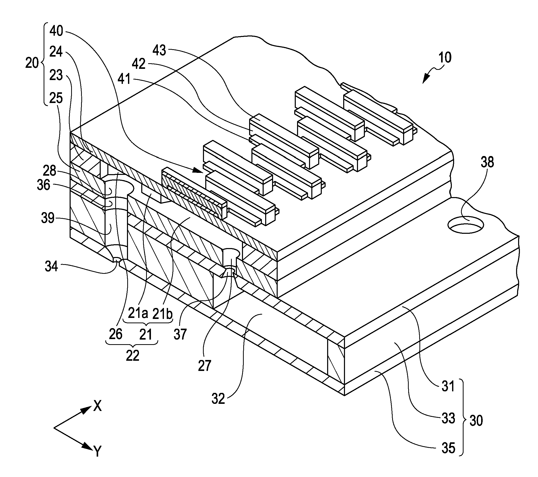
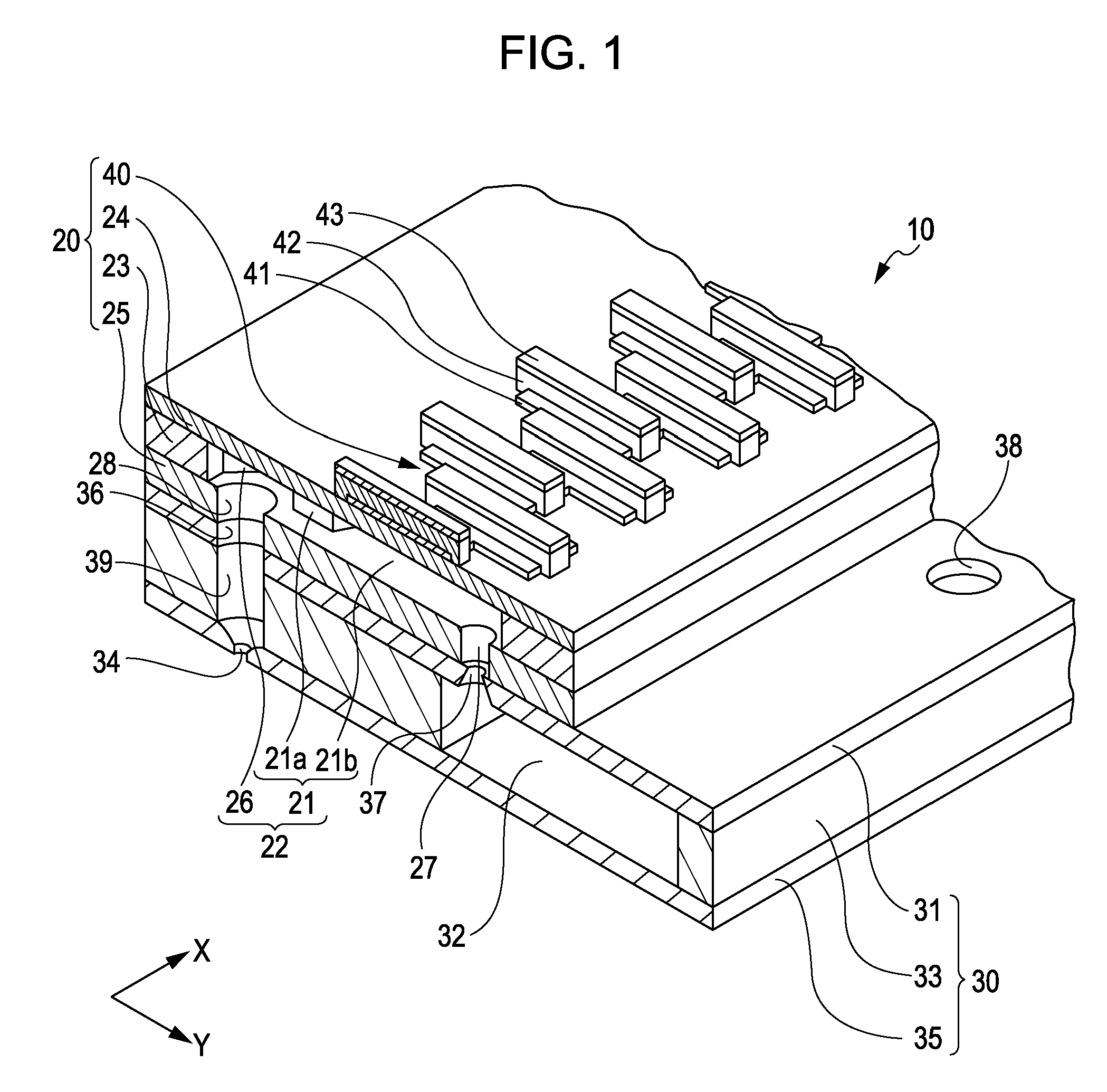
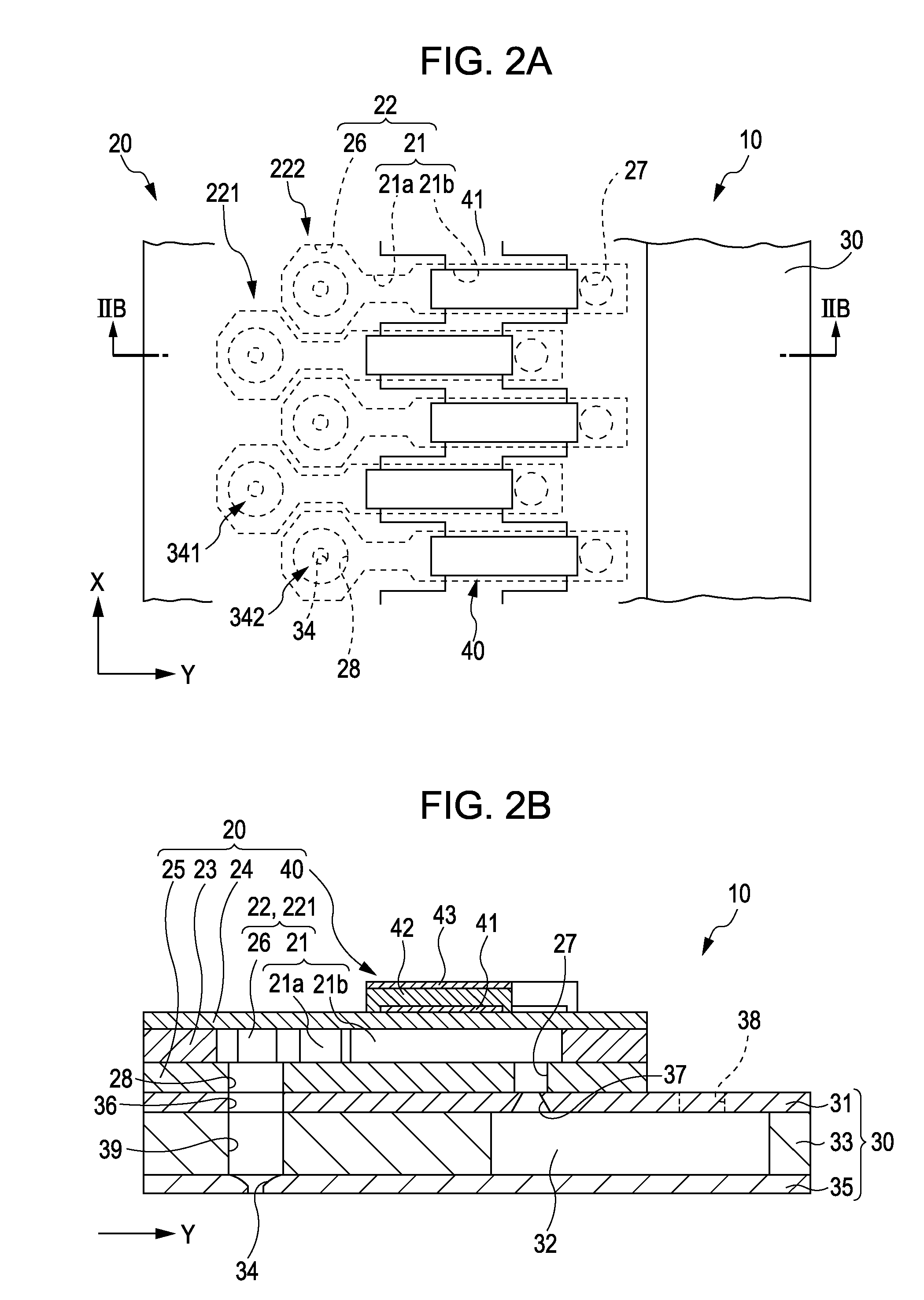
[0025]FIG. 1 is a perspective view obtained by cutting away major portions of an inkjet recording head which indicates an example of a liquid ejection head according to a first embodiment of the invention, FIG. 2A is a plan view showing a piezoelectric element side of an inkjet recording head and FIG. 2B is a cross-sectional view taken along line IIB-IIB of the piezoelectric element, and FIG. 3 is a plan view showing an individual flow path of an inkjet recording head.

[0026]As shown in the drawings, an inkjet recording head 10 according to the present embodiment includes an actuator unit 20 and a flow path unit 30 in which the actuator unit 20 is fixed.

[0027]The actuator unit 20 is an actuator device including a piezoelectric element 40, and includes a flow path forming substrate 23 on which a pressure generating chamber 21 is formed, a vibration plate 24 provided on one surface side of the flow path forming substrate 23, and a pressure generating chamber bottom plate 25 provided on...


PUM


Abstract

A liquid ejection head includes a nozzle plate, and a flow path member that is bonded to the nozzle plate, wherein the individual flow path includes a communicating portion that communicates with the nozzle openings and a pressure generating chamber that communicates with the communicating portion and has a width narrower than that of the communicating portion in the first direction, and wherein, in the flow path member, a first individual flow path row in which corresponding individual flow paths are arranged side by side in the first direction and a second individual flow path row where corresponding individual flow paths are arranged side by side in the first direction are arranged side by side in a second direction intersecting with the first direction, and each communicating portion of the second individual flow path row is provided between the pressure generating chambers of the first individual flow path row.

Description

BACKGROUND[0001]1. Technical Field[0002]The present invention relates to a liquid ejection head and a liquid ejection device which eject a liquid from nozzle openings, and particularly, to an inkjet recording head and an inkjet recorder which eject ink as a liquid.[0003]2. Related Art[0004]As a representative example of a liquid ejection head, for example, an inkjet recording head that ejects ink droplets from nozzle openings by causing a pressure change in ink in a pressure generating chamber communicating with the nozzle openings has been known.[0005]In the inkjet recording head, in order to very densely arrange the nozzle openings, so-called staggered arrangement in which a first nozzle row in which the nozzle openings are arranged side by side in a first direction and a second nozzle row in which the nozzle openings are arranged in a second direction intersecting with the first direction offset in the first direction so as not to be in the same position in the second direction h...

Claims


Application Information

Patent Timeline
Patent Type & Authority Applications(United States)
IPC IPC(8): B41J2/05
CPCB41J2202/11B41J2/14233
Inventor HOTTA, AKIRA
Owner SEIKO EPSON CORP
Why Eureka
Try Eureka