Liquid ejection device

a liquid ejection device and liquid ejection technology, applied in the direction of optical radiation measurement, instruments, spectrometry/spectrophotometry/monochromators, etc., can solve the problem and achieve the effect of deteriorating accuracy of color measurement of color meter

Active Publication Date: 2013-01-17
SEIKO EPSON CORP
View PDF3 Cites 2 Cited by
  • Summary
  • Abstract
  • Description
  • Claims
  • Application Information

AI Technical Summary

Benefits of technology

[0007]In a case of providing both of the light irradiating section and the color meter as described above, however, it is likely that light radiated from the irradiating section will be reflected on a medium and the like, and will enter the color meter. Then, the color measurement value of the color meter might be changed by the effect of light from the irradiating section. Consequently, the accuracy of the color measurement of the color meter might be deteriorated.

Problems solved by technology

Consequently, the accuracy of the color measurement of the color meter might be deteriorated.

Method used


Image

  • Liquid ejection device
  • Liquid ejection device
  • Liquid ejection device

Examples


first embodiment

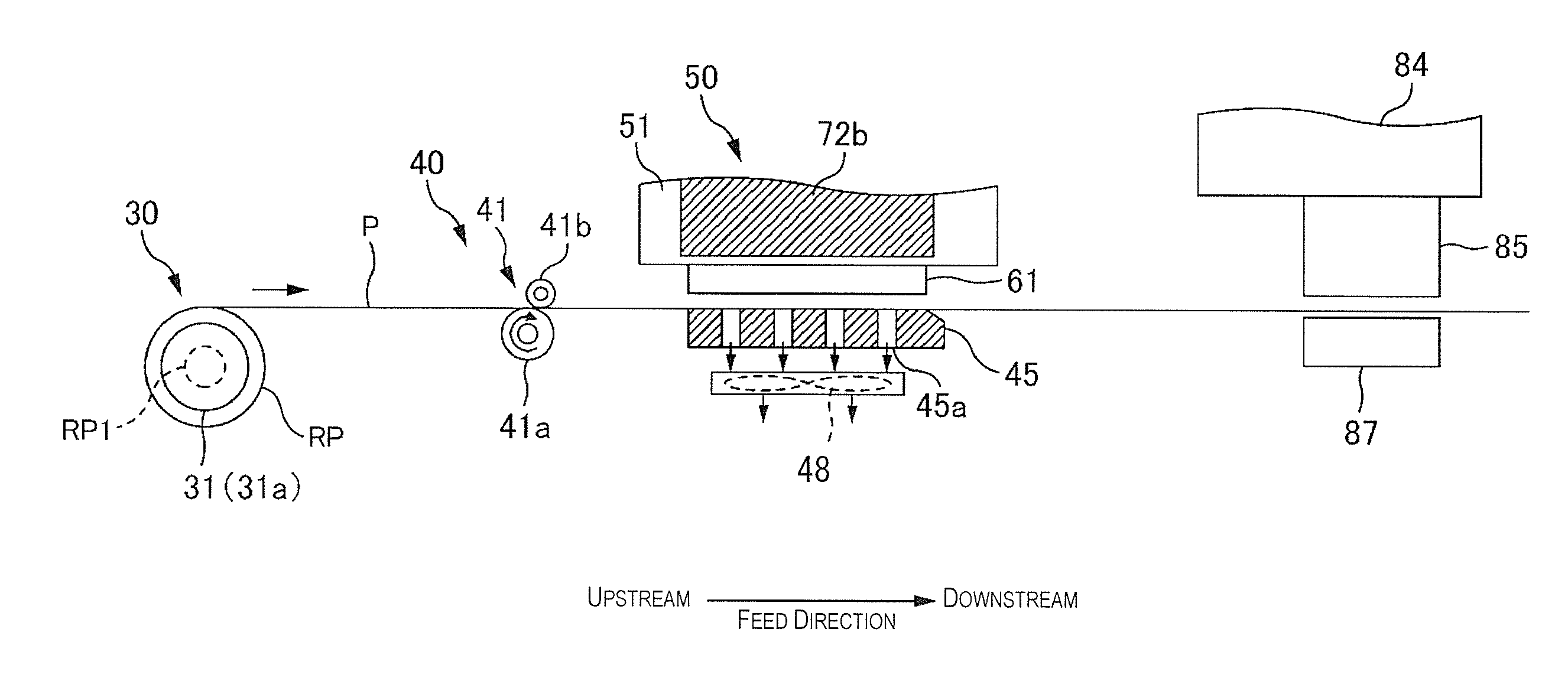
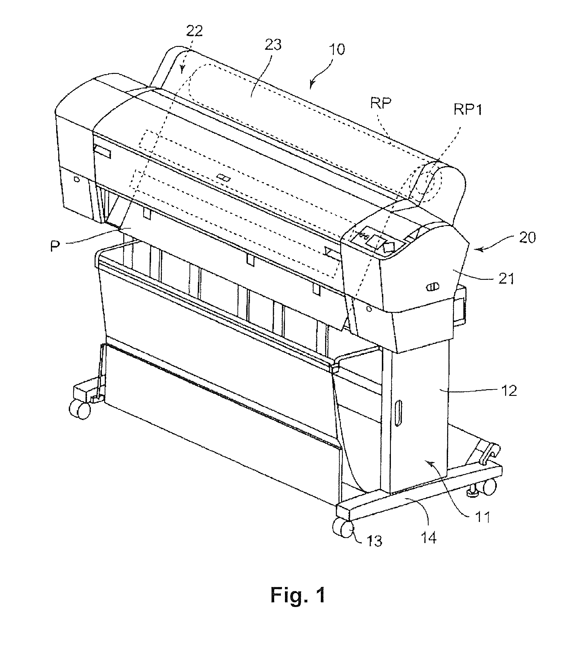
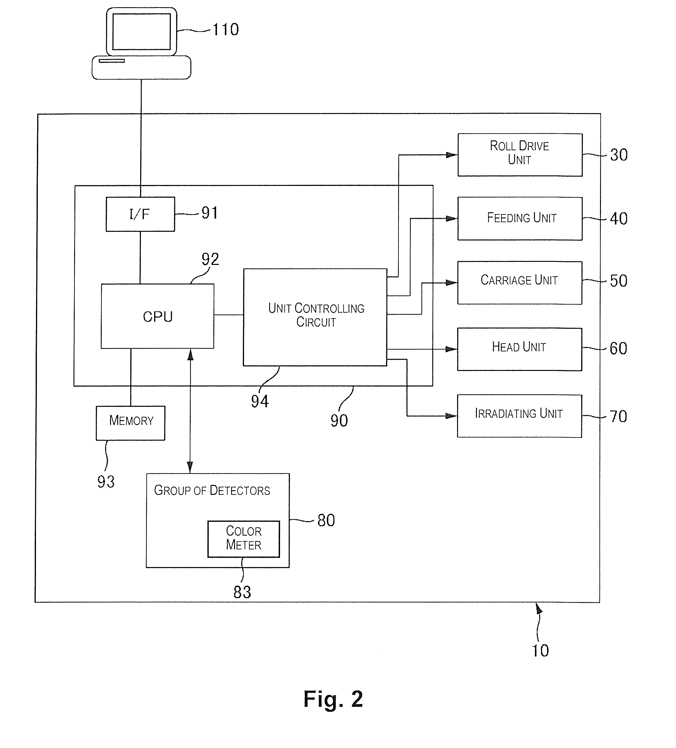
[0034]Hereinafter, the printer 10 of the present embodiment will be explained. The printer 10 of the present embodiment is a printer for printing to a large-sized medium (for example, paper having a size of A2 or larger according to the Japanese Industrial Standard). The printer 10 of the present embodiment prints an image to a medium by ejecting UV curable ink (hereinafter, UV ink), as an example of a liquid, to be cured when irradiated with ultraviolet rays (hereinafter, UV) that is one type of light. UV ink is ink that contains UV curable resin, and when irradiated with UV, a photopolymerization reaction occurs in the UV curable resin, which causes the UV ink to cure. The printer 10 of the present embodiment prints an image by using UV ink of four colors of CMYK. In the following explanation, the lower side refers to a side where the printer 10 is installed, and the upper side refers to a side apart from the side where the printer 10 is installed. Also, the paper feeding side (ba...

second embodiment

[0083]In the second embodiment, the accuracy of color measurement is improved by further eliminating the effect of UV irradiation at the time of the color measurement. In the second embodiment, UV irradiation is performed at the time of calibration in the same manner as the first embodiment. Also, the configuration of the second embodiment that is the same as one of the first embodiment has the same reference numbers, and will not be explained.

[0084]FIG. 10 is a diagram explaining a state of feeding paper P in the second embodiment. As shown in the drawing, the printer 10 of the second embodiment has a bending roller 46 and a pair of paper discharge rollers 47.

[0085]The bending roller 46 is a roller for bending paper P toward a normal direction of the platen 45 (direction shown by the dotted line in the drawing). The direction of paper P in the feed direction is changed by the bending roller 46. As shown in FIG. 10, the bending roller 46 is positioned between the platen 45 (that is,...

third embodiment

[0091]In the above-described embodiments, the print conditions (print speed and UV irradiation conditions) are the same whether or not the color meter 83 performs color measurement. In the third embodiment, however, the UV irradiation intensity of the irradiating section 72a (72b) and the print speed are changed. Incidentally, in the third embodiment, UV irradiation from the irradiating section 72a (72b) is performed at the time of calibration in the same manner as in the first embodiment.

[0092]For example, the moving speed of the carriage 51 at the time of printing is made smaller in a case where the color meter 83 performs color measurement (than in a case where the color meter 83 does not perform color measurement). Consequently, the UV irradiation intensity of the irradiating section 72a (72b) can be set to be low. In this case, although the UV irradiation intensity of the irradiating section 72a (72b) becomes low, the UV irradiation time to dots becomes long because the moving ...


PUM


Abstract

A liquid ejection device has a feeding mechanism, a nozzle, an irradiating section, and a color meter. The feeding mechanism is configured and arranged to feed a medium in a feed direction. The nozzle is configured and arranged to eject a liquid to be cured by irradiation of light toward the medium. The irradiating section is configured and arranged to radiate the light toward the liquid landed on the medium. The color meter is disposed on a downstream side of the feed direction with respect to the irradiating section so as to perform color measurement of an image generated on the medium, the color meter being configured and arranged such that calibration of the color meter is performed by reading a reference. The irradiating section is configured and arranged to radiate the light when the calibration of the color meter is performed.

Description

CROSS-REFERENCE TO RELATED APPLICATIONS[0001]This application claims priority to Japanese Patent Application No. 2011-154125 filed on Jul. 12, 2011. The entire disclosure of Japanese Patent Application No. 2011-154125 is hereby incorporated herein by reference.BACKGROUND[0002]1. Technical Field[0003]The present invention relates to a liquid ejection device.[0004]2. Related Art[0005]As an example of a liquid ejection device, a printer for printing an image by ejecting a liquid (such as UV ink) to be cured by irradiation of light (such as UV) is known. Such a printer has a light irradiating section which radiates light toward a liquid (dots) landed on a medium after the liquid is ejected from a nozzle to the medium. In this manner, the dots are cured and fixed to the medium, which makes it possible to perform good printing to a medium that is difficult to absorb a liquid.[0006]Another printer is also known in which a color meter is provided on a downstream side of a feed direction of ...

Claims


Application Information

Patent Timeline
Patent Type & Authority Applications(United States)
IPC IPC(8): B41J2/01
CPCH04N1/6044G01J3/524B41J11/002B41J11/0021B41J11/00214
Inventor USUDA, HIDENORI
Owner SEIKO EPSON CORP
Why Eureka
Try Eureka