Timepiece movement comprising a module fitted with a wheel set meshing with another wheel set pivoting in a base on which the module is mounted

a timepiece and module technology, applied in the field of timepiece movement, can solve the problems of reducing the rate of the timepiece movement, affecting the balance of the instrument,

Active Publication Date: 2013-01-17
ETA SA MFG HORLOGERE SUISSE
View PDF4 Cites 9 Cited by
  • Summary
  • Abstract
  • Description
  • Claims
  • Application Information

AI Technical Summary

Problems solved by technology

This gives rise to a real problem for the rate of the timepiece movement, since, if the gearing of the first and second wheel sets is not optimal, efficiency is reduced and becomes variable.
The amplitude of the balance is generally reduced and this affects the rate accuracy of the timepiece.
It is not generally possible to position the module by a simple vertical translation.
The assembly tolerances of the escape wheel set and wheel 14 in the platform escapement and on the bottom plate respectively mean that it is not possible to obtain a precise, predetermined distance of centres.
Moreover, the assembly of the platform escapement on the bottom plate has a large tolerance which considerably increases the problem.
Generally, when a module, which forms a distinct unit with at least a first wheel set pivoting therein, is arranged on a timepiece movement base and the first wheel set has to mesh with a second wheel set pivoting on the base, there is a problem linked to the fact that the distance of centres of the first and second wheel sets varies around the optimum distance of centres; which affects the proper operation of the timepiece movement.
Indeed, the gearing between the first and second wheel sets is made worse by numerous manufacturing tolerances; particularly with the modular construction provided here.
It is therefore difficult to obtain a predetermined distance of centres.

Method used


Image

  • Timepiece movement comprising a module fitted with a wheel set meshing with another wheel set pivoting in a base on which the module is mounted
  • Timepiece movement comprising a module fitted with a wheel set meshing with another wheel set pivoting in a base on which the module is mounted
  • Timepiece movement comprising a module fitted with a wheel set meshing with another wheel set pivoting in a base on which the module is mounted

Examples


Embodiment Construction

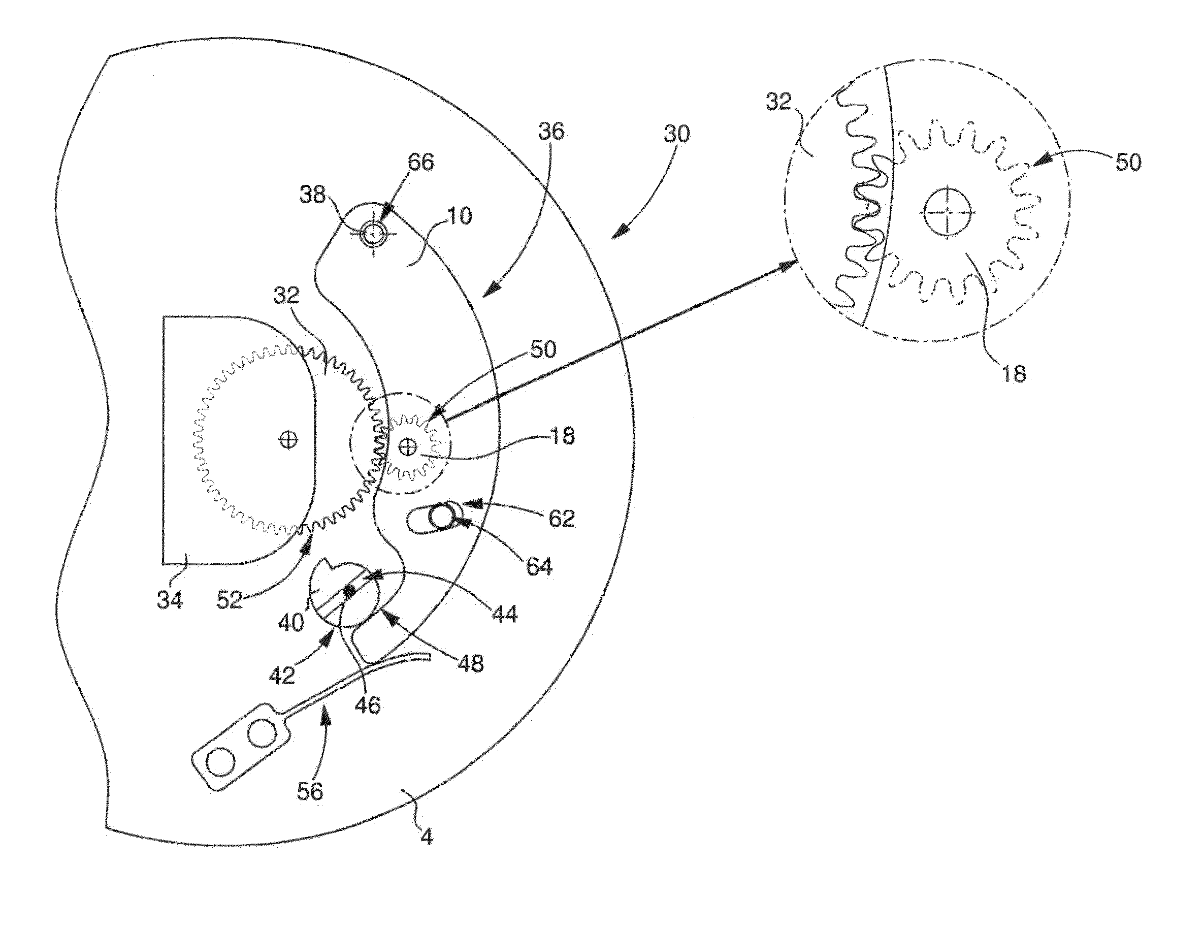
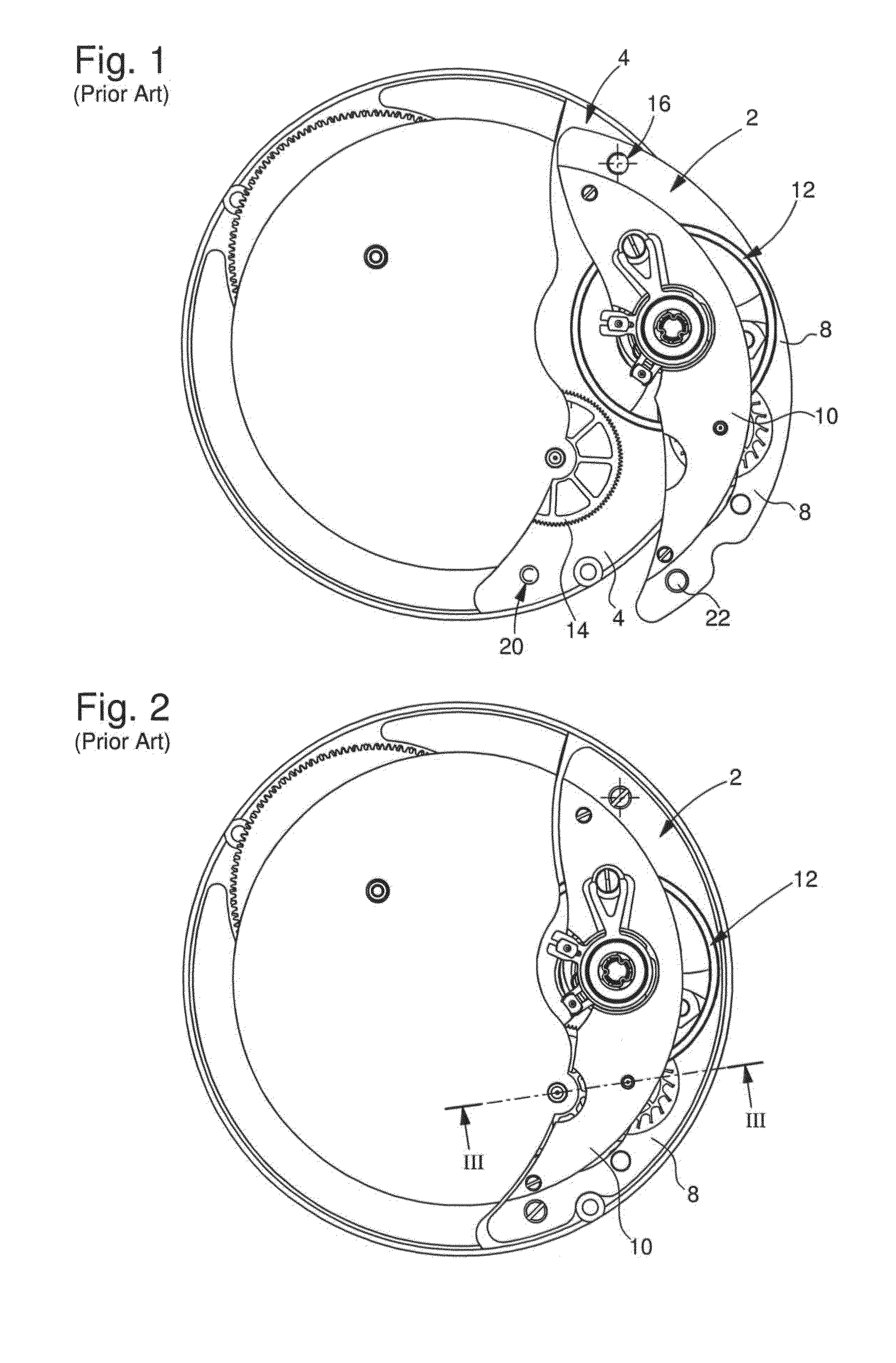
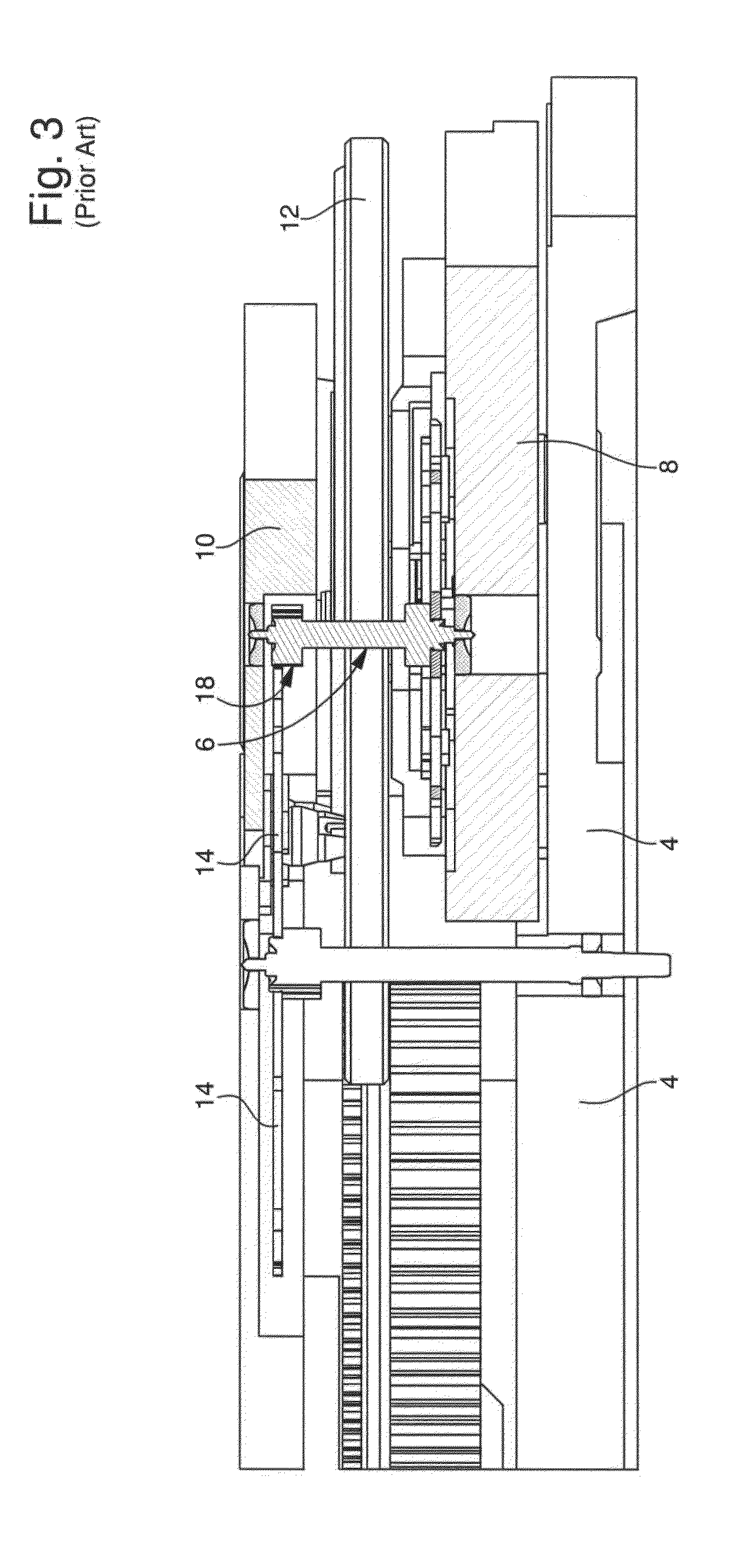
[0018]With reference to FIGS. 4 to 6, a timepiece movement of the aforementioned type will be schematically described with reference to FIGS. 1 to 3, but incorporating the present invention. The timepiece movement 30 is partially shown. There is shown, on the one hand, the fourth wheel 32, which is pivotally mounted between bottom plate 4 and a bar 34, and, on the other hand, a platform escapement 36 carrying an escape wheel set of which only the escape pinion 18 is shown. This is sufficient to describe the present invention.

[0019]According to a first implementation of the method of adjusting the distance of centres L between a first timepiece wheel set 18, pivotally mounted in a module 36, which is able to undergo rotation about a geometric axis 38 relative to a base 4 on which it is mounted, and a second timepiece wheel set 32, which pivots on the base, there is arranged on the base a cam 40, at least most of the periphery 42 of which forms an Archimedes' spiral or an optimized Ar...


PUM


Abstract

Timepiece movement including a module fitted with a first wheel set meshing with a second wheel set, which pivots on a base on which the module is mounted. The movement includes a means of positioning the module formed by a cam, at least most of the periphery of which forms an Archimedes' spiral. The cam is arranged so as to allow the distance of centres between the first and second wheel sets to be adjusted, when the cam is rotated on itself about the centre of the Archimedes' spiral. The cam is preferably calibrated. The invention also concerns a method of adjusting the distance of centres between the two wheel sets using said cam to optimise the gearing efficiency of the two wheel sets.

Description

FIELD OF THE INVENTION[0001]The present invention concerns a timepiece movement comprising a module fitted with a first wheel set meshing with a second wheel set which pivots in a base on which the module is mounted. In particular, the invention concerns a timepiece movement including a platform escapement which forms a module in which the escapement is arranged, i.e. the sprung balance, the pallet fork and the escape wheel set. This escape wheel set is formed of an escapement plate and an escape pinion which, in the finished movement, meshes with a gear train wheel mounted on the bottom plate to which the platform escapement is fixed.BACKGROUND OF THE INVENTION[0002]When there is no particular problem in fixing the module to the base of the timepiece movement, particularly to the bottom plate, by a vertical translation which enables a first wheel set of the module to mesh with a second wheel set pivoting in the base, the module is generally positioned by two feet (or pins) machined...

Claims


Application Information

Patent Timeline
Patent Type & Authority Applications(United States)
IPC IPC(8): G04B15/00
CPCG04B29/00
Inventor MOULIN, JULIENVILLAR, IVANKAELIN, LAURENTWYSSBROD, BAPTIST
Owner ETA SA MFG HORLOGERE SUISSE
Why Eureka
Try Eureka