Filling system for filling a travel dispenser

a technology for filling systems and dispensers, which is applied in the direction of liquid handling, single-unit apparatuses, packaging goods types, etc., can solve the problems of not easy to determine when the reservoir of the travel dispenser is full, the pump is electrical, and thus needs electrical power

Inactive Publication Date: 2013-01-24
APTAR FRANCE SAS
View PDF12 Cites 22 Cited by
  • Summary
  • Abstract
  • Description
  • Claims
  • Application Information

AI Technical Summary

Benefits of technology

[0022]One of the principles of the present invention resides in using a base that incorporates a manual pump and an actuator member, on which base there are mounted both a supply and the travel dispenser to be refilled. Another principle of the invention lies in a single actuation of the actuator member leading to correct and constant filling of the reservoir of the travel dispenser, starting from a completely empty state.

Problems solved by technology

Thus, it is not easy to determine when the reservoir of the travel dispenser is full.
There is thus a risk of filling it only in part, or of filling it too much, which can cause leaks.
The drawback of this filling system is that the pump is electrical and thus needs an electrical power.

Method used


Image

  • Filling system for filling a travel dispenser
  • Filling system for filling a travel dispenser
  • Filling system for filling a travel dispenser

Examples


first embodiment

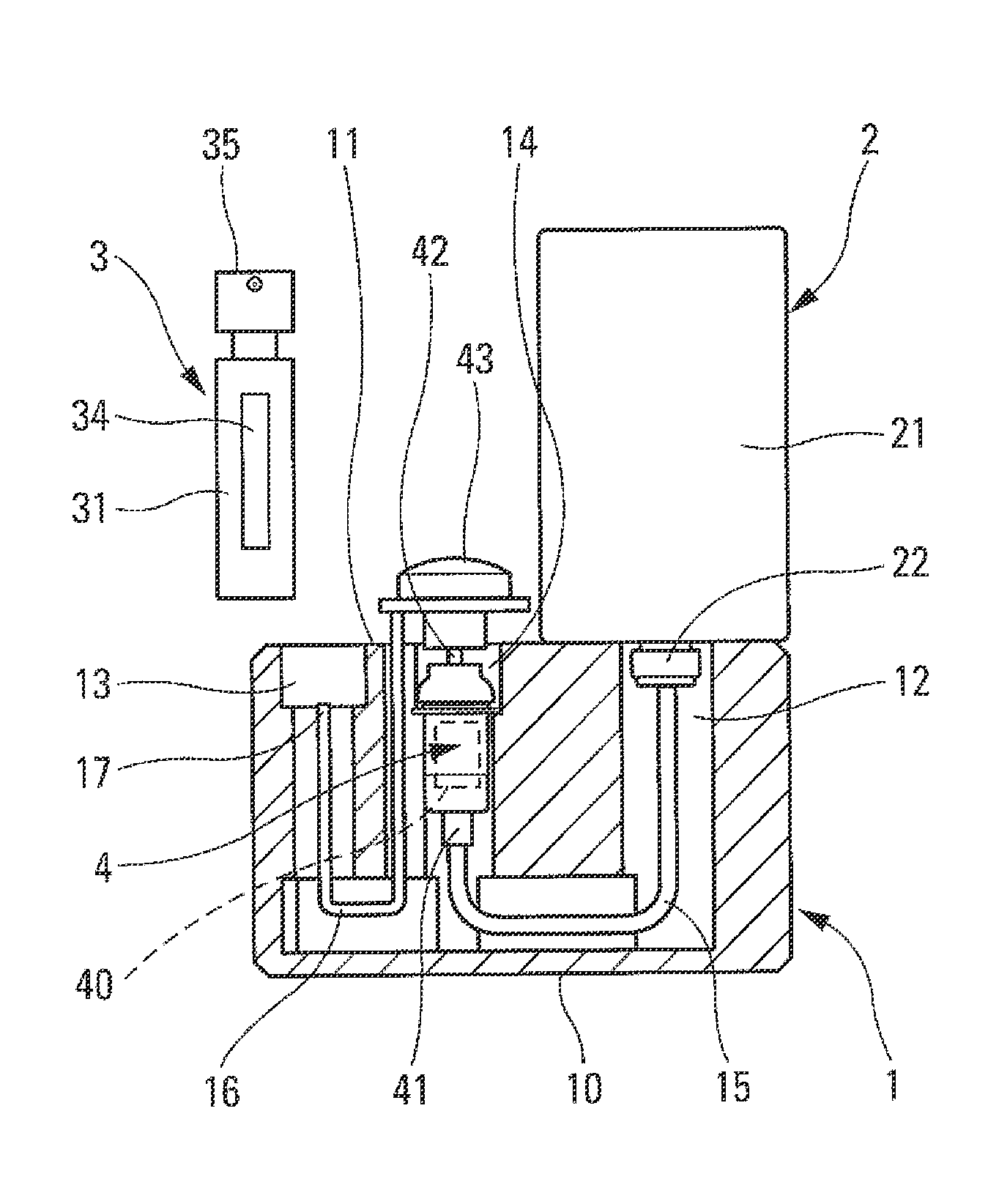
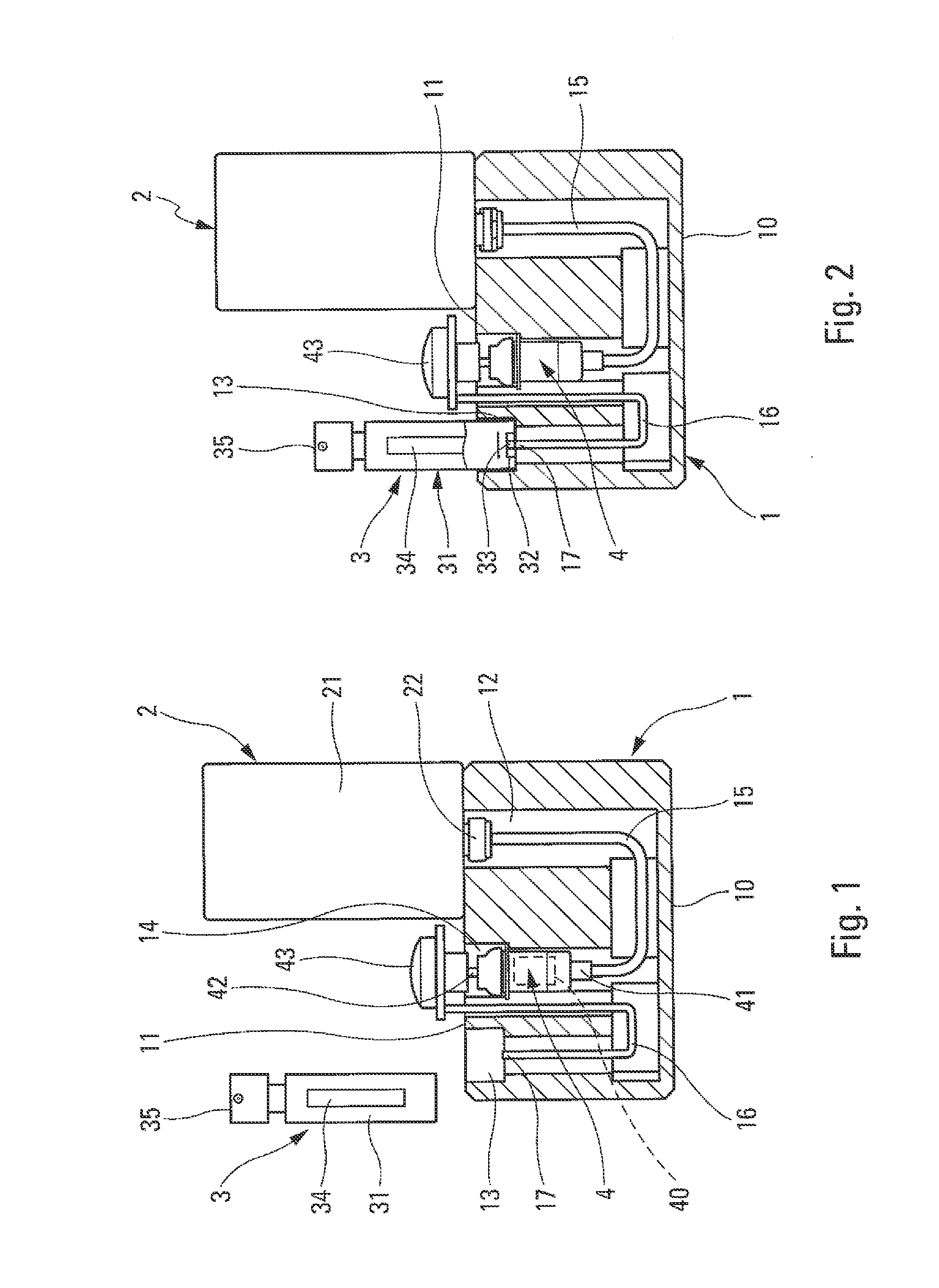
[0029]In the first embodiment in FIGS. 1 and 2, the pump defines an inlet 41 that is connected to the supply 2 via the duct 15. The pump defines a pump chamber 40 presenting its maximum volume in its rest position. The pump 4 also includes an actuator rod 42 on which there is mounted a pusher 43 that acts as an actuator member. The duct 16 is connected to the pusher 43, or, in a variant, to another component element of the pump 4. By pressing on the pusher 43, fluid is taken from the supply 2 via the duct 15, and is delivered to the duct 16 having its end 17 opening the check valve 33 of the filling orifice 32 of the reservoir 31 of the travel dispenser 3. Advantageously, the maximum volume of the pump chamber 40 corresponds substantially to the determined maximum volume of the reservoir 31 of the travel dispenser, such that the reservoir 31 may be filled with a single actuation of the pusher 43. By way of example, provision may be made for the maximum volume of the chamber 40 to be...

second embodiment

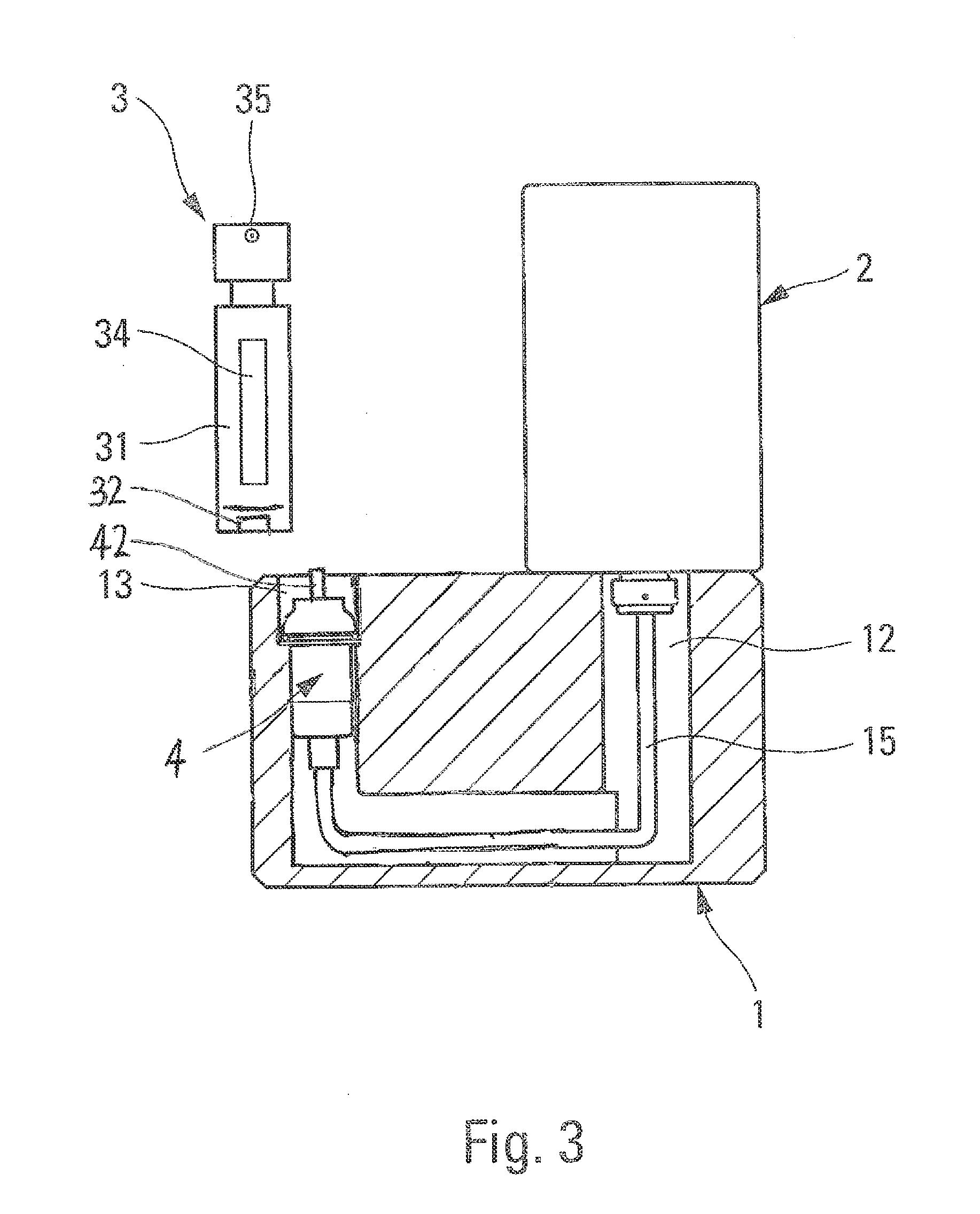
[0031]In the second embodiment in FIG. 3, the manual pump 4 is connected to the fluid supply 2 by a duct 15 and is located in the filling housing 13. The manual pump 4 comprises an actuator rod 42 that acts as an actuator member. The actuator rod 42 is located in the filling housing 13, in such a manner as to be actuated by the insertion of the travel dispenser. Thus, when the travel dispenser is pushed inside the filling housing 13 of the base 1, the actuator rod is depressed and the pump 4 dispenses a fluid product dose which corresponds roughly or precisely to the volume of the reservoir 31 of the travel dispenser. The travel dispenser is thus again refilled with fluid product.

[0032]Therefore, when starting from a completely empty state, the user does not even need to worry about how the dispenser means need to be actuated in order to fill the reservoir of the travel dispenser. Merely placing or inserting the travel dispenser in its filling housing 13 suffices to cause it to be f...


PUM

PropertyMeasurementUnit
volumeaaaaaaaaaa
sizeaaaaaaaaaa
period of timeaaaaaaaaaa

Abstract

A filling system for filling a travel dispenser comprising:
    • a base (1);
    • a fluid supply (2) that is mounted on the base (1); and
    • a travel dispenser (3) including a reservoir (31) that is provided with a filling orifice (32), the reservoir defining a determined maximum volume, the travel dispenser (3) being received in removable manner in a filling housing (13) that is defined by the base (1);
    • wherein the base (1) comprises:
      • a manual pump (4) for taking fluid from the supply (2) and delivering it through the filling orifice (32) into the reservoir (31) of the travel dispenser (3); and
      • an actuator member (43; 42) for actuating the manual pump (4),
    • said system being characterized in that the manual pump (4) defines a pump chamber (40) having a maximum volume that is substantially equal to the determined maximum volume of the reservoir (31) of the travel dispenser (3), such that, from a completely empty state, the reservoir of the travel dispenser (3) is filled by pressing once on the pusher (43).

Description

CROSS REFERENCE TO RELATED APPLICATION[0001]This application claims the benefit under 35 U.S.C. §119(e) of pending U.S. provisional patent application Ser. No. 61 / 534,593, filed Sep. 14, 2011, and priority under 35 U.S.C. §119(a)-(d) of French patent application No. FR11 56609, filed Jul. 21, 2011.TECHNICAL FIELD[0002]The present invention relates to a filling system for filling a travel dispenser, namely a low-capacity dispenser that can easily be carried, in particular while traveling. Advantageous fields of application of the present invention are the fields of perfumery, cosmetics, or even pharmacy.[0003]“Travel” dispensers are used increasingly in the field of perfumery so as to enable users to apply the same perfume as the perfume of the dispenser that is left at home. Conventional dispensers include a medium- capacity reservoir, such that carrying such dispensers is not always easy. In addition, current regulations on air transport greatly limit the quantity of liquid that ma...

Claims


Application Information

Patent Timeline
Patent Type & Authority Applications(United States)
IPC IPC(8): B65B3/04
CPCB65B3/12B05B11/0056
Inventor FERIANI, AMIRMULLER, PATRICK
Owner APTAR FRANCE SAS
Why Eureka
Try Eureka