Modular indirect suspended/ceiling mount fixture

a module and indirect technology, applied in the field oftroffer-style lighting fixtures, can solve the problems of very energy-inefficient incandescent lights, relatively inefficient leds, and leds can have a significantly longer operational li

Active Publication Date: 2013-01-24
IDEAL IND LIGHTING LLC
View PDF24 Cites 102 Cited by
  • Summary
  • Abstract
  • Description
  • Claims
  • Application Information

AI Technical Summary

Problems solved by technology

Incandescent lights are very energy-inefficient light sources with approximately ninety percent of the electricity they consume being released as heat rather than light.
Fluorescent light bulbs are more energy efficient than incandescent light bulbs by a factor of about 10, but are still relatively inefficient.
In addition, LEDs can have a significantly longer operational lifetime.
Incandescent light bulbs have relatively short lifetimes, with some having a lifetime in the range of about 750-1000 hours.
Fluorescent bulbs can also have lifetimes longer than incandescent bulbs such as in the range of approximately 10,000-20,000 hours, but provide less desirable color reproduction.
High power LEDs can draw large currents, generating significant amounts of heat that must be managed.
This can present challenges as plenum space decreases in modern structures.
Furthermore, the temperature in the plenum area is often several degrees warmer than the room environment below the ceiling, making it more difficult for the heat to escape into the plenum ambient.

Method used


Image

  • Modular indirect suspended/ceiling mount fixture
  • Modular indirect suspended/ceiling mount fixture
  • Modular indirect suspended/ceiling mount fixture

Examples


Embodiment Construction

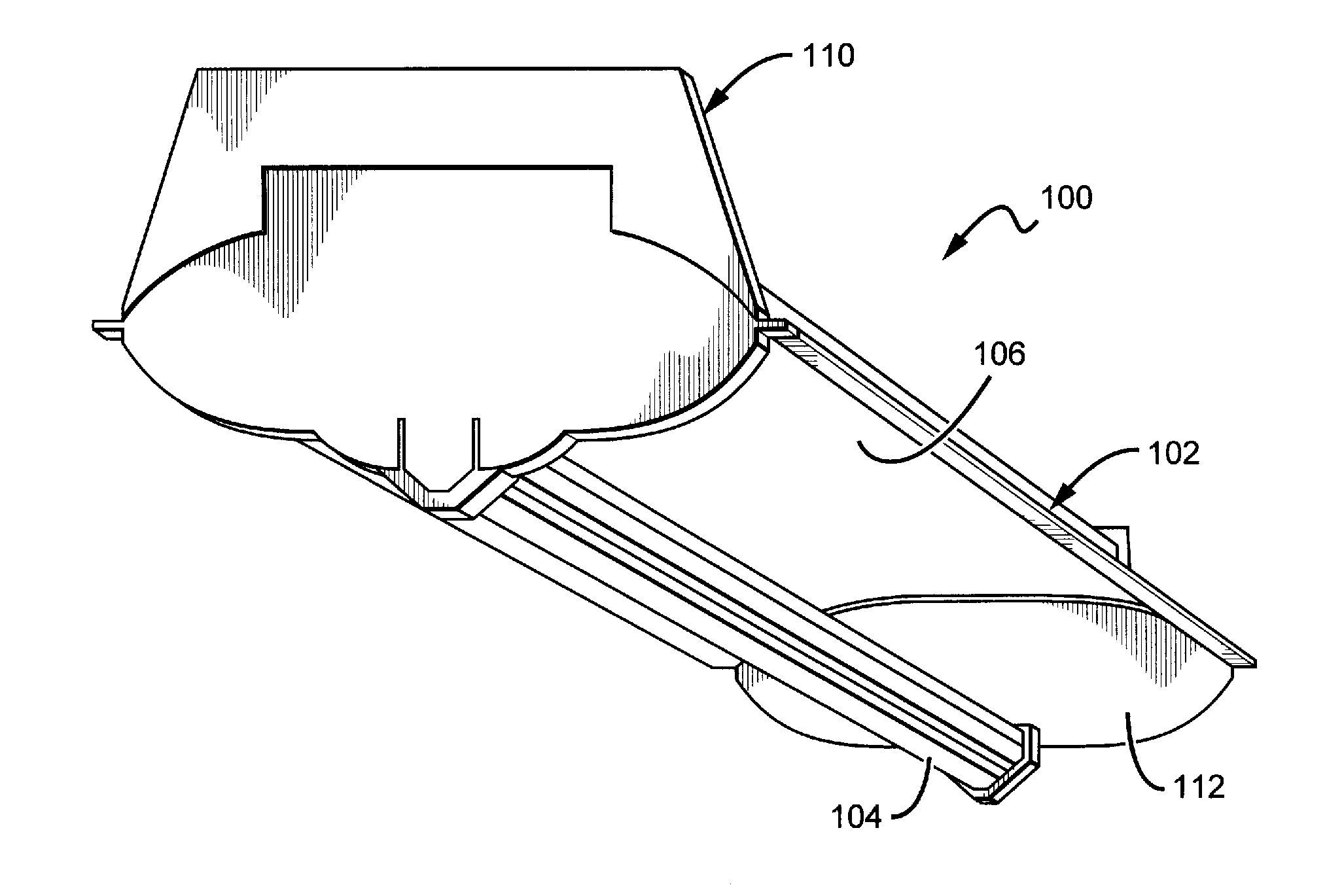
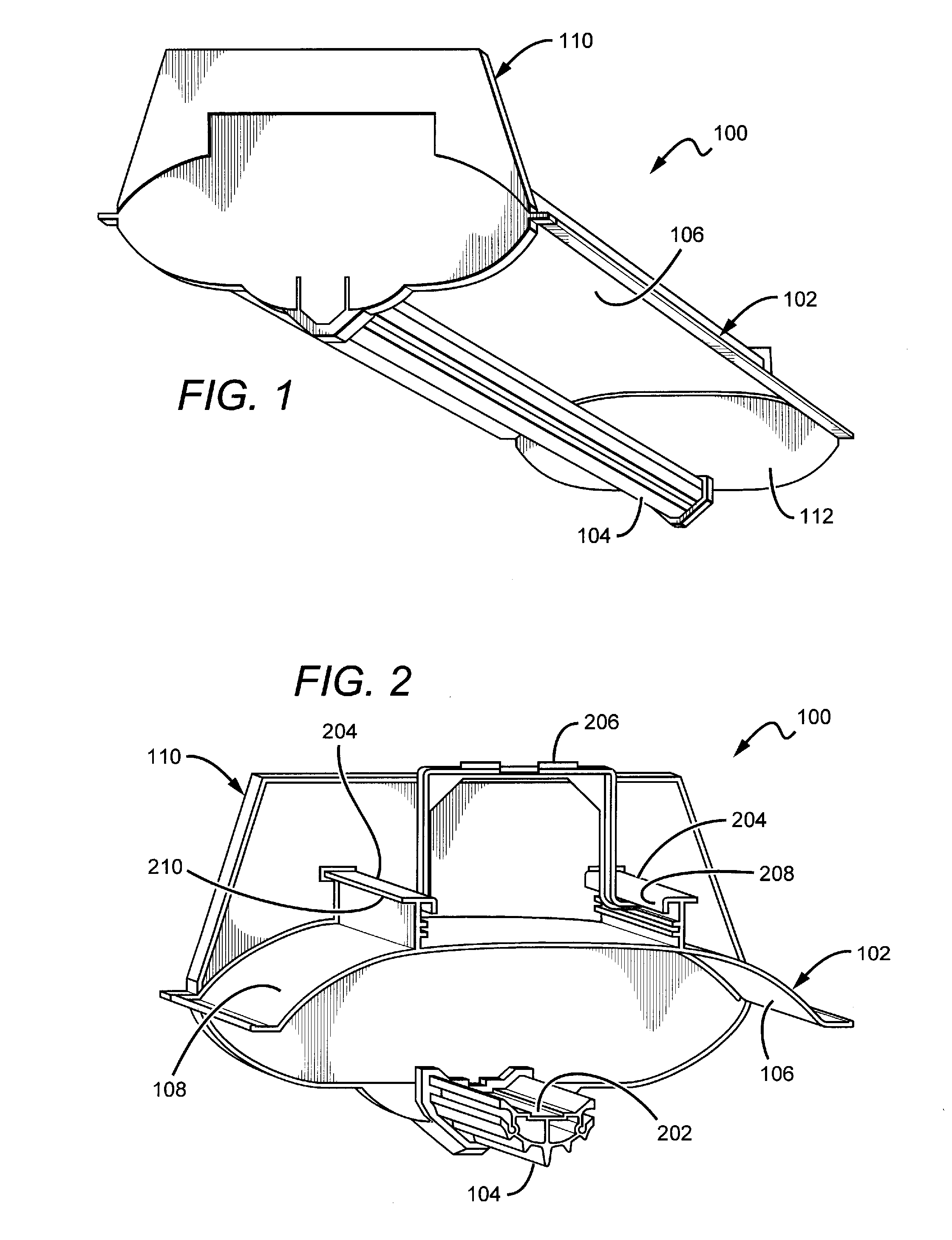
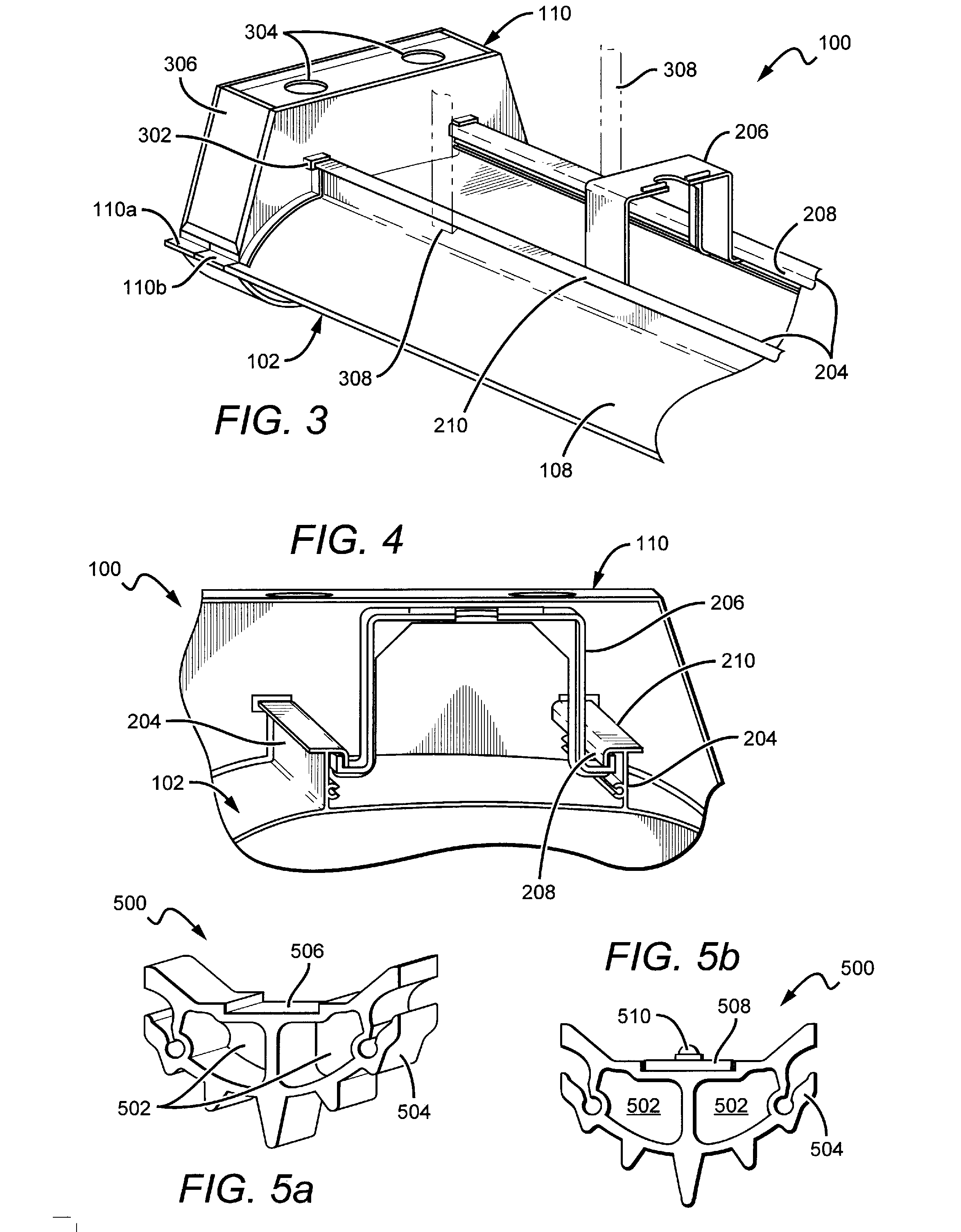
[0028]Embodiments of the present invention provide a modular troffer-style fixture that is particularly well-suited for use with solid state light sources, such as LEDs. The fixture comprises a reflector having a surface on one side and a back surface on the opposite side. The back surface includes parallel rails that run along the length of the reflector, providing a mount mechanism as well structural support to the reflector. To facilitate the dissipation of unwanted thermal energy away from the light sources, a heat sink is disposed proximate to the surface of the reflector. The portion of the heat sink facing the reflector functions as a mount surface for the light sources, creating an efficient thermal path from the sources to the ambient. The heat sink, which is exposed to the ambient room environment, is hollow through the center in the longitudinal direction. The hollow portion defines a conduit through which electrical conductors (e.g., wires) can be run to power light emit...


PUM

PropertyMeasurementUnit
correlated color temperatureaaaaaaaaaa
distancesaaaaaaaaaa
lengthsaaaaaaaaaa

Abstract

A modular troffer-style fixture particularly well-suited for use with solid state light sources. The fixture comprises a reflector that includes parallel rails running along its length, providing a mount mechanism and structural support. An exposed heat sink is disposed proximate to the reflector. The portion of the heat sink facing the reflector functions as a mount surface for the light sources. The heat sink is hollow through the center in the longitudinal direction. The hollow portion defines a conduit through which electrical conductors can be run to power light emitters. One or more light sources disposed along the heat sink mount surface emit light toward the reflector where it can be mixed and/or shaped before it is emitted from the troffer as useful light. End caps are arranged at both ends of the reflector and heat sink, allowing for the easy connection of multiple units in a serial arrangement.

Description

BACKGROUND[0001]1. Field[0002]The invention relates to troffer-style lighting fixtures and, more particularly, to troffer-style fixtures that are well-suited for use with solid state lighting sources, such as light emitting diodes (LEDs).[0003]2. Description of the Related Art[0004]Troffer-style fixtures are ubiquitous in commercial office and industrial spaces throughout the world. In many instances these troffers house elongated fluorescent light bulbs that span the length of the troffer. Troffers may be mounted to or suspended from ceilings. Often the troffer may be recessed into the ceiling, with the back side of the troffer protruding into the plenum area above the ceiling. Typically, elements of the troffer on the back side dissipate heat generated by the light source into the plenum where air can be circulated to facilitate the cooling mechanism. U.S. Pat. No. 5,823,663 to Bell, et al. and U.S. Pat. No. 6,210,025 to Schmidt, et al. are examples of typical troffer-style fixtur...

Claims


Application Information

Patent Timeline
Patent Type & Authority Applications(United States)
IPC IPC(8): F21V29/00
CPCF21S2/00F21V29/70F21S8/06F21S9/02F21V7/0008F21V15/015F21V21/005F21V23/002F21V23/007F21Y2101/02F21Y2103/003F21Y2113/005F21V29/004F21S8/026F21S8/043F21S8/063F21V7/0016F21V7/22F21V15/01F21V15/013F21V21/112F21S4/008F21S4/28F21Y2103/10F21Y2115/10F21Y2113/13F21V29/85F21V7/28F21V7/24
Inventor SNELL, NATHANLAY, JAMES MICHAELNGUYEN, NICKO'FLAHERTY, PATRICK JOHN
Owner IDEAL IND LIGHTING LLC
Why Eureka
Try Eureka