
Cadence detection for interlaced video based on temporal regularity

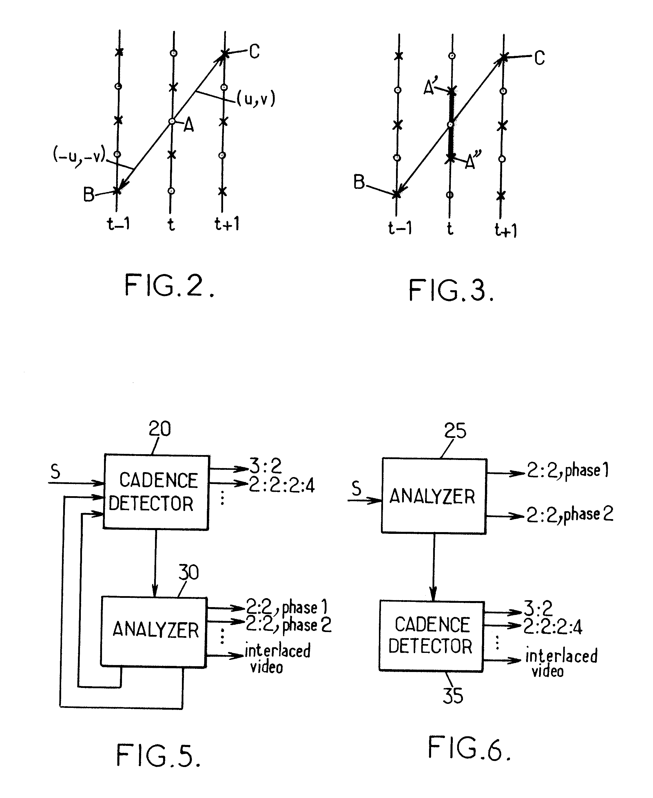
a technology of temporal regularity and interlaced video, applied in the field ofcadence detection of interlaced video based on temporal regularity, can solve the problems of difficult film cadence detection, the detection of time correlation cannot be used to detect 2:2 pulldown, and the problem of deinterlacing arises, so as to achieve efficient detection of 2:2 cadence and improve performan

Inactive Publication Date: 2013-01-24
ZORAN CORPORATION
View PDF7 Cites 2 Cited by
  • Summary
  • Abstract
  • Description
  • Claims
  • Application Information

AI Technical Summary

Benefits of technology

The proposed method described in the patent text is a new and improved way to detect video frames with spatial and temporal regularity. This method can be used in combination with traditional methods to increase its strength and accuracy, especially when the video contains sharp content with high vertical frequencies. The method involves estimating the regularity of a video frame by calculating a metric based on a sum of minimum loss values from reference pixels. This sum is computed over a set of candidate displacements and a loss function that takes into account pixels values from at least two fields with different ranks in the video. The technical effect of this invention is an improved and more robust ability to detect video frames with high accuracy, which can aid in various applications such as video analysis and classification.

Problems solved by technology

Obviously the problem of deinterlacing arises for 50i or 60i contents only.
However, this kind of detection with time correlation cannot be used to detect 2:2 pulldown which is the most difficult film cadence to detect.
On frames with high frequency contents however, these assumptions do not hold and thus the algorithms do not correctly detect the 2:2 cadence.

Method used


Image

  • Cadence detection for interlaced video based on temporal regularity
  • Cadence detection for interlaced video based on temporal regularity
  • Cadence detection for interlaced video based on temporal regularity

Examples


Embodiment Construction

[0046]An input video signal consists of a sequence of fields having integer ranks t. The signal can be considered as an array of pixels Ft(x, y), where x and y are the horizontal and vertical coordinates of the pixels and t is the rank of the field Ft, x and y being also represented as integers. To account for the interlaced form of the signal, we assume that for some parity p=0 or p=1, all the pixels Ft(x, y) for which (y+t)=p (mod 2) have a value provided in the field sequence while pixels Ft(x, y) for which (y+t)≠p (mod 2) are unknown or have a special value of “NA” (“not available”). In the following, Ft is used a short notation to denote the video field at time t.

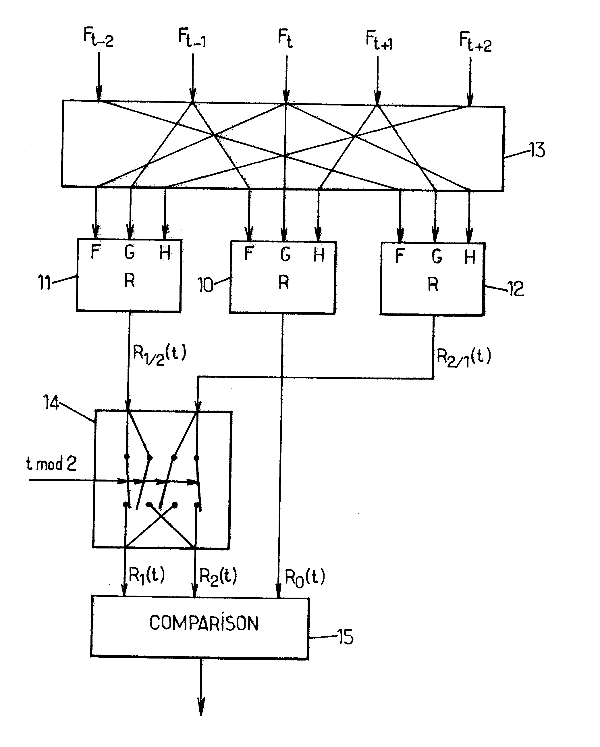
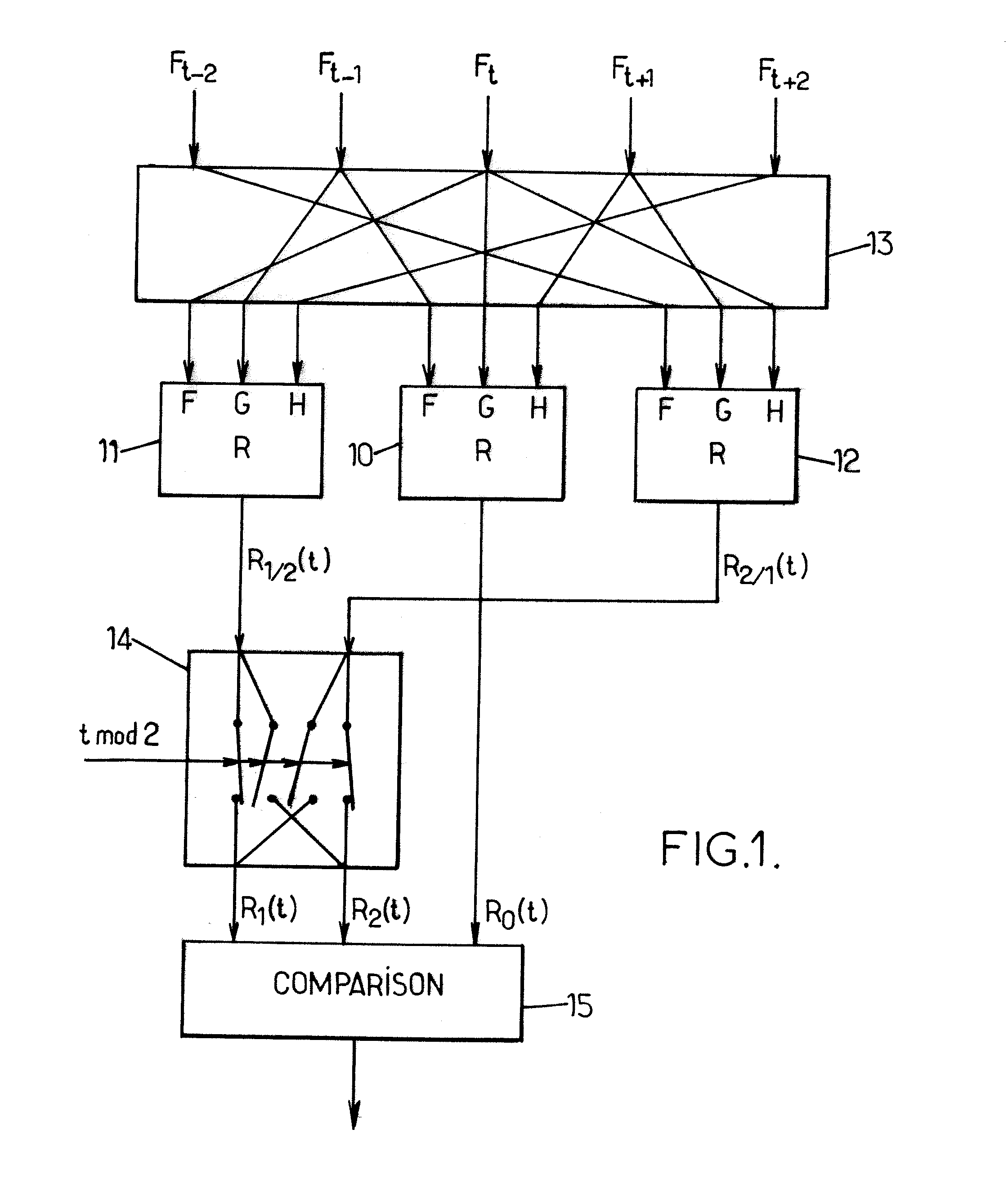
[0047]The block diagram of FIG. 1 illustrates the proposed method of analyzing the interlaced video signal S, in an exemplary embodiment. At the input of the analyzer, five consecutive fields Ft−2, Ft−1, Ft, Ft+1 and Ft+2 (or more) are received in view of computing three metric values with respect to time t:[0048]a fir...


PUM


Abstract

A method is proposed for analyzing an interlaced video signal including a first sequence of fields. A temporal regularity estimation process is applied to the first sequence of fields to compute a first metric. Inputs of the temporal regularity estimation process include pixel values from at least two fields having respective ranks differing by more than one in the sequence. The same temporal regularity estimation process is applied to second and third sequences of fields to compute second and third metrics. The second sequence is derived from the first sequence by swapping fields having ranks of the form 2k and 2k+1 for any integer k, while the third sequence is derived from the first sequence by swapping fields having ranks of the form 2k−1 and 2k. The first, second and third metrics are compared in a determination of the time arrangement of the fields in the first sequence.

Description

BACKGROUND OF THE INVENTION[0001]The present invention relates to the technology of video signal processing and more particularly to analysis methods usable to determine the arrangement in time of the fields forming an interlaced video signal.[0002]Such analysis methods are useful for detecting the cadence of the interlaced video signal, which is an important detection to decide which processing should be applied to the signal for display. From the following discussion, it will be seen that the determination of the time arrangement of the fields in the sequence may also involve other aspects such as detecting certain spurious field inversions.[0003]Current television standards (e.g. PAL, NTSC, 1080i, . . . ) use interlaced signals, with frames split into two fields, one containing the odd lines of the frame and the other one containing the even lines. A deinterlacer using line duplication or interpolation is used when the display or other processing applied to the signal needs to re...

Claims


Application Information

Patent Timeline
Patent Type & Authority Applications(United States)
IPC IPC(8): G06K9/68
CPCH04N5/145H04N21/440281H04N7/012H04N7/0115
Inventor BRUNA ESTRACH, JOAN
Owner ZORAN CORPORATION
Learn More