
Safety system, a method of operating a safety system and a method of building a safety system

a safety system and inductive power technology, applied in the direction of electric devices, rail devices, transportation and packaging, etc., can solve the problems of dangerous heating of foreign objects, power loss and heating of objects, and it is not possible to mechanically prevent foreign objects, so as to increase the robustness of detection and quick and reliable detection of foreign objects

Active Publication Date: 2018-08-28
BOMBARDIER TRANSPORTATION GMBH
View PDF37 Cites 0 Cited by
  • Summary
  • Abstract
  • Description
  • Claims
  • Application Information

AI Technical Summary

Benefits of technology

The patent text describes an arrangement of detection windings that can reliably detect objects in a predetermined surface area, which can also be referred to as a surveillance area, of a route. Another embodiment involves emitting a radar or microwave signal along the charging surface and receiving the reflected signal using at least one microwave receiving device to conduct radar- or microwave-based object detection based on the received signal. This method ensures reliable and robust detection.

Problems solved by technology

A problem in such devices is that it is generally not possible to mechanically prevent foreign objects, in particular objects made of metal, from being placed into proximity of the primary unit of an inductive power transfer system.
Such currents may cause power losses and heating of the object.
Heating of the foreign objects made be dangerous for example to persons trying to touch and remove the foreign object and / or may damage the surface the foreign object is placed on or parts of the primary unit.
Also, a heated object can cause fire.

Method used


Image

  • Safety system, a method of operating a safety system and a method of building a safety system
  • Safety system, a method of operating a safety system and a method of building a safety system
  • Safety system, a method of operating a safety system and a method of building a safety system

Examples


first embodiment

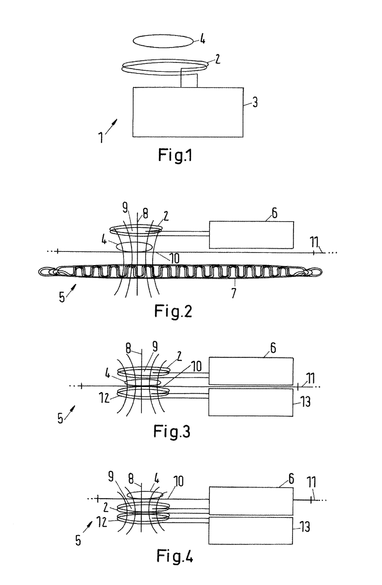
[0142]FIG. 2 shows a proposed safety system 5 in a The safety system 5 comprises a detection winding 2, a voltage sensor 6 and a primary winding structure 7 of a primary unit of a system for inductive power transfer to a vehicle (not shown). The primary winding structure 7 consists of three individual phase lines which extend in a meandering manner in a direction of travel of vehicles driving on the surface of the route 11 (longitudinal direction). In the embodiment shown, the primary winding structure 7 serves as an excitation winding which generates an alternating electromagnetic excitation field which is symbolized by field lines 8. It is shown that a magnetic flux extends through a detection surface 9 of the detection winding 2. The magnitude of the magnetic flux will change depending on the presence of an object 4 in the proximity of the detection winding 2. It is shown that the detection winding 2 is arranged such that the object 4, which is located on a charging surface 10 o...

fourth embodiment

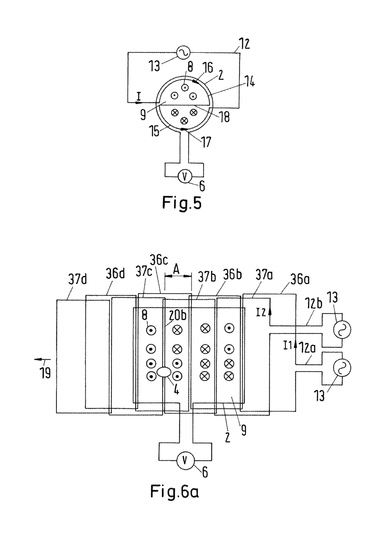
[0168]FIG. 9 shows a schematic diagram of the proposed safety system 5 in a A voltage generator 13 is operated at the resonant frequency of an oscillating circuit, wherein losses of the oscillating circuit are compensated by the voltage source 13. The oscillating circuit is provided by a resonant capacitive element Cres and an excitation winding 12. The elements of the oscillating circuit are designed such that the oscillating circuit provides an infinite impedance with respect to the voltage source 13.

[0169]Within the oscillating circuit, a resonant current Ires flows. This resonant current Ires generates an excitation field which is received by the detection winding 2, wherein the detection winding 2 generates a relatively high voltage which can be detected by a voltage sensor 6. If a foreign object (not shown) is placed within the proximity of the excitation winding 12, the oscillating circuit is detuned. In this case, the resonant frequency of the oscillating circuit does not m...

fifth embodiment

[0175]FIG. 11 shows a schematic diagram of the proposed safety system 5 in a In this case, the detection winding 2 is part of an LC oscillating circuit. As shown in FIG. 9, a voltage generator 13 is operated at the resonant frequency of the oscillating circuit, wherein losses of the oscillating circuit are compensated by the voltage source 13. The oscillating circuit is provided by a resonant capacitive element Cres and the detection winding 2. Again, the elements of the oscillating circuit are designed such that the oscillating circuit provides an infinite impedance with respect to the voltage source 13. Within the oscillating circuit, a resonant current Ires flows. This resonant current Ires generates a voltage falling across the parallel connection of the capacitive element Cres and the detection winding 2. If a foreign object (not shown) is placed within the proximity of the detection winding 2, the oscillating circuit is detuned. In this case, the resonant frequency of the osc...


PUM

PropertyMeasurementUnit
poweraaaaaaaaaa
electromagnetic primary fieldaaaaaaaaaa
magnetic fluxaaaaaaaaaa

Abstract

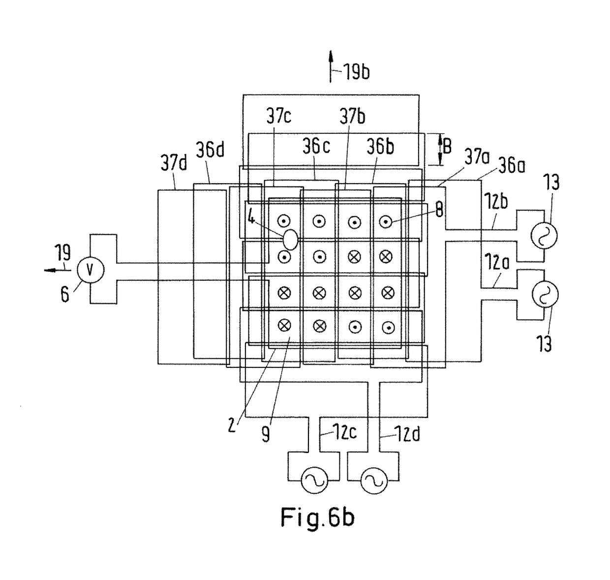
The invention relates to a safety system for an inductive power transfer system for transferring power to a vehicle on a surface of a route, wherein the primary unit comprises at least one primary winding for generating an electromagnetic primary field for the inductive power transfer, wherein a charging surface of the route is assigned to the primary winding. The safety system comprises at least one inductive sensing system, wherein the inductive sensing system comprises multiple detection windings wherein the multiple detection windings are arranged in an array structure, and wherein the array structure covers the charging surface at least partially. Furthermore, the invention relates to a method of operating such a safety system and a method of building such a safety system.

Description

CROSS-REFERENCE TO RELATED APPLICATIONS[0001]This application is the United States national phase of International Application No. PCT / EP2013 / 076705 filed Dec. 16, 2013, and claims priority to United Kingdom Patent Application No. 1222712.0 filed Dec. 17, 2012, the disclosures of which are hereby incorporated in their entirety by reference.BACKGROUND OF THE INVENTION[0002]Field of the Invention[0003]The invention relates to a safety system for an inductive power transfer system, in particular an inductive power transfer system for transferring electric energy to a vehicle which is standing or travelling on a surface of a route. Furthermore, the invention relates to a method of operating such a safety system and a method of building such a safety system.[0004]Description of Related Art[0005]WO 2012 / 047779 A1 discloses a safety system for a charger to provide protection with respect to an object that may become hot during operation of the charger, wherein the safety system comprises a...

Claims


Application Information

Patent Timeline
Patent Type & Authority Patents(United States)
IPC IPC(8): B60L11/18B60L3/00H02J5/00B60M1/04B60M7/00B60L5/00H02J50/60H02J50/70H02J50/10H01F38/14
CPCB60L11/182B60L5/005B60L11/1837B60M1/04B60M7/003H01F38/14H02J5/005H02J50/10H02J50/60H02J50/70B60L3/00Y02T90/14B60L2200/18B60L2200/26B60L2200/36Y02T10/7005Y02T10/7072Y02T90/121Y02T90/122Y02T90/128B60L53/32B60L53/124B60L53/122H02J2310/48H02J7/0042Y02T10/70Y02T90/12H02J50/12H02J7/025B60L53/12
Inventor CZAINSKI, ROBERT
Owner BOMBARDIER TRANSPORTATION GMBH
Learn More