
ECG electrode system

a biomedical electrode and electrode technology, applied in the field of biomedical electrode connectors and radiolucent lead wires, can solve the problems of obfuscating the visual images of clinicians and surgeons, ferrous and/or magnetic components commonly found in ecg connectors, such as springs and clips, and may be potentially hazardous

Inactive Publication Date: 2013-01-24
TYCO HEALTHCARE GRP LP
View PDF0 Cites 21 Cited by
  • Summary
  • Abstract
  • Description
  • Claims
  • Application Information

AI Technical Summary

Benefits of technology

The patent describes a system for easily attaching electrodes to a patient during medical imaging procedures using a special ECG lead set and extension cable. This system is designed to be radiolucent, meaning it can be seen on images obtained from MRI, CT, or PET scanners. The use of these special leads and connectors helps to improve the accuracy and reliability of ECG readings during these procedures. The technical effect of this system is to provide a safer and more reliable way of performing ECGs during medical imaging procedures.

Problems solved by technology

Use of conventional ECG connectors and lead wire sets typically associated therewith may have drawbacks in these applications, since they tend to interfere with the imaging systems.
In one example, certain components of the ECG connectors and / or lead wires may be detected by the imaging apparatus and consequently may obfuscate the visual images upon which clinicians and surgeons rely.
In another example, ferrous and / or magnetic components commonly found in ECG connectors, such as in springs and clips, may be potentially hazardous when used within the intense magnetic field of an MRI scanner.

Method used


Image

  • ECG electrode system
  • ECG electrode system
  • ECG electrode system

Examples


Embodiment Construction

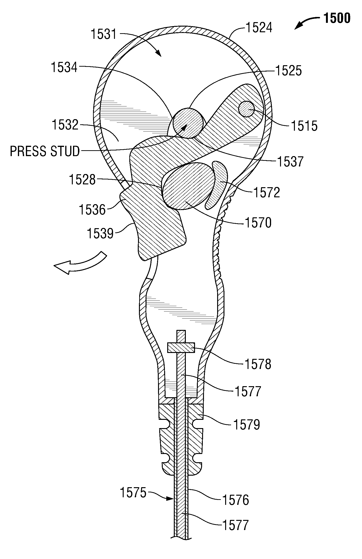
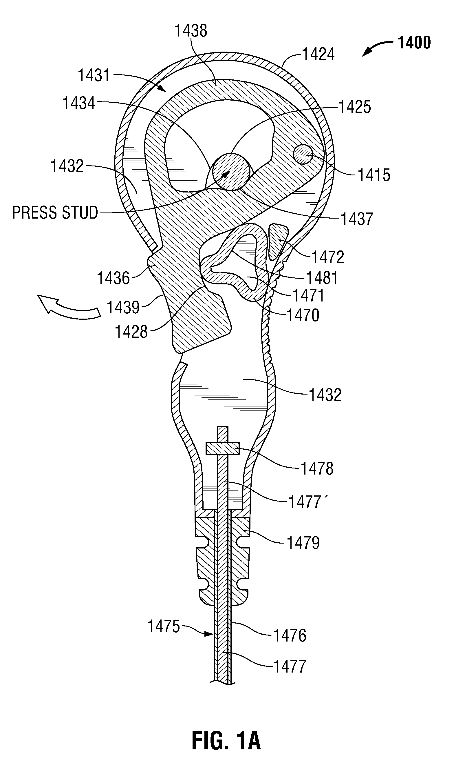
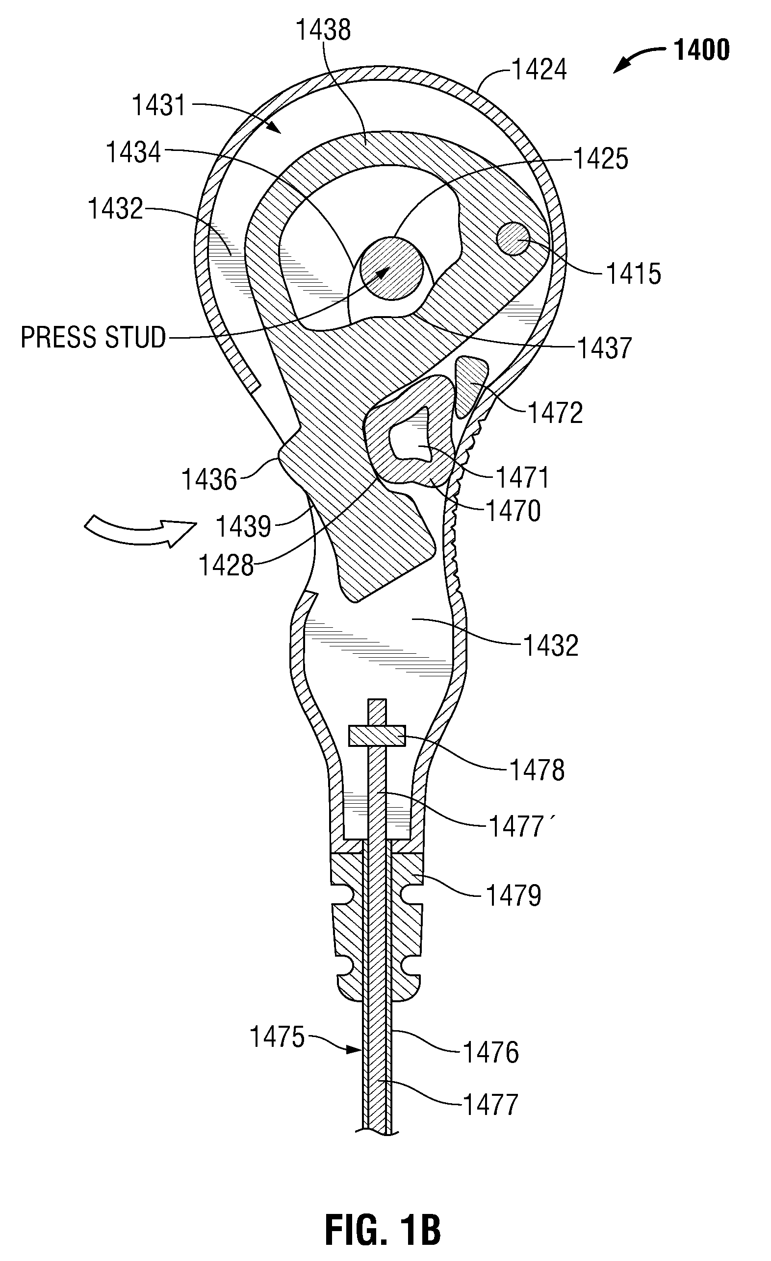
[0021]Particular embodiments of the present disclosure are described hereinbelow with reference to the accompanying drawings; however, the disclosed embodiments are merely examples of the disclosure, which may be embodied in various forms. Well-known functions or constructions and repetitive matter are not described in detail to avoid obscuring the present disclosure in unnecessary or redundant detail. Therefore, specific structural and functional details disclosed herein are not to be interpreted as limiting, but merely as a basis for the claims and as a representative basis for teaching one skilled in the art to variously employ the present disclosure in virtually any appropriately detailed structure. In this description, as well as in the drawings, like-referenced numbers represent elements which may perform the same, similar, or equivalent functions.

[0022]In the drawings and in the descriptions that follow, the term “proximal,” as is traditional, shall refer to the end of the in...


PUM


Abstract

An ECG electrode lead system suitable for use during imaging procedures such as, without limitation, CT scans or MRI and methods of use. The a radiolucent ECG lead set cable includes at least one radiolucent conductor, at least one radiolucent electrode connector operatively coupled to a distal end of the ECG lead set cable, an ECG intermediate lead set connector disposed at a proximal end of the ECG lead set cable, and an ECG lead extension assembly.

Description

CROSS-REFERENCE TO RELATED APPLICATION[0001]This application claims the benefit of and priority to U.S. Provisional Application Ser. No. 61 / 510,527, filed on Jul. 22, 2011, the entire contents of which is hereby incorporated by reference herein for all purposes.BACKGROUND[0002]1. Technical Field[0003]The present disclosure relates to biomedical electrodes, and in particular, to a radiolucent biomedical electrode connector and radiolucent lead wires for performing biomedical monitoring of a patent during imaging procedures.[0004]2. Background of Related Art[0005]Electrocardiograph (ECG) monitors are widely used to obtain medical (i.e. biopotential) signals containing information indicative of the electrical activity associated with the heart and pulmonary system. To obtain medical signals, ECG electrodes are applied to the skin of a patient in various locations. The electrodes, after being positioned on the patient, connect to an ECG monitor by a set of ECG lead wires. The distal end...

Claims


Application Information

Patent Timeline
Patent Type & Authority Applications(United States)
IPC IPC(8): A61B5/0408A61B5/308
CPCA61B5/04286A61B5/04085A61B2562/17A61B5/303A61B5/282
Inventor CALLAHAN, MARK J.
Owner TYCO HEALTHCARE GRP LP
Learn More