Power supply system

a power supply system and power supply technology, applied in the direction of electric devices, process and machine control, instruments, etc., can solve the problems of solar power and off-grid power

Active Publication Date: 2013-01-24
DENSO CORP +1
View PDF1 Cites 52 Cited by
  • Summary
  • Abstract
  • Description
  • Claims
  • Application Information

AI Technical Summary

Problems solved by technology

The consumption of the solar power results from at least one of a charge of the power storing device, a consumption in the load, and a discharge back to the grid.
T

Method used


Image

  • Power supply system
  • Power supply system
  • Power supply system

Examples


embodiment

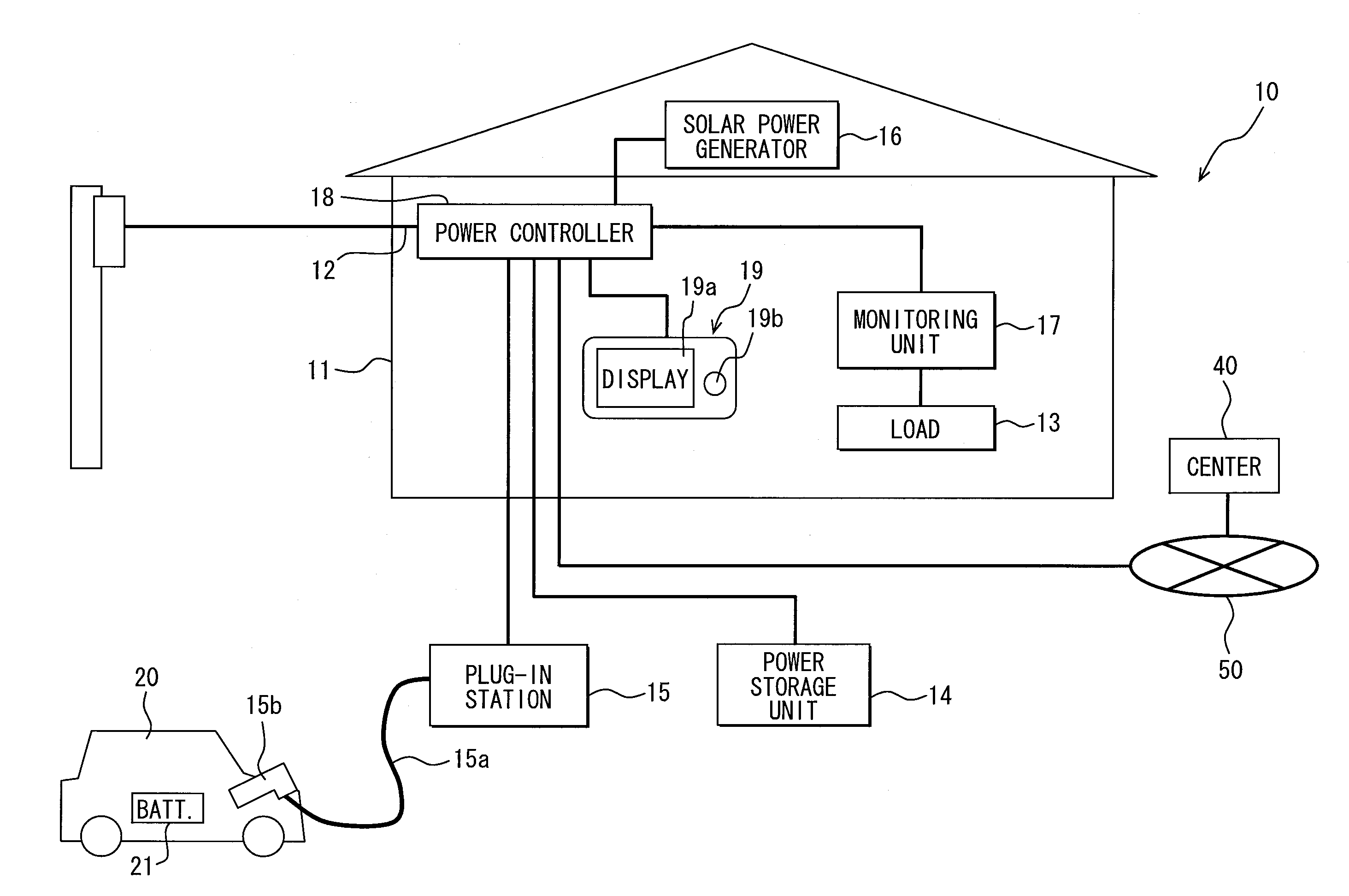
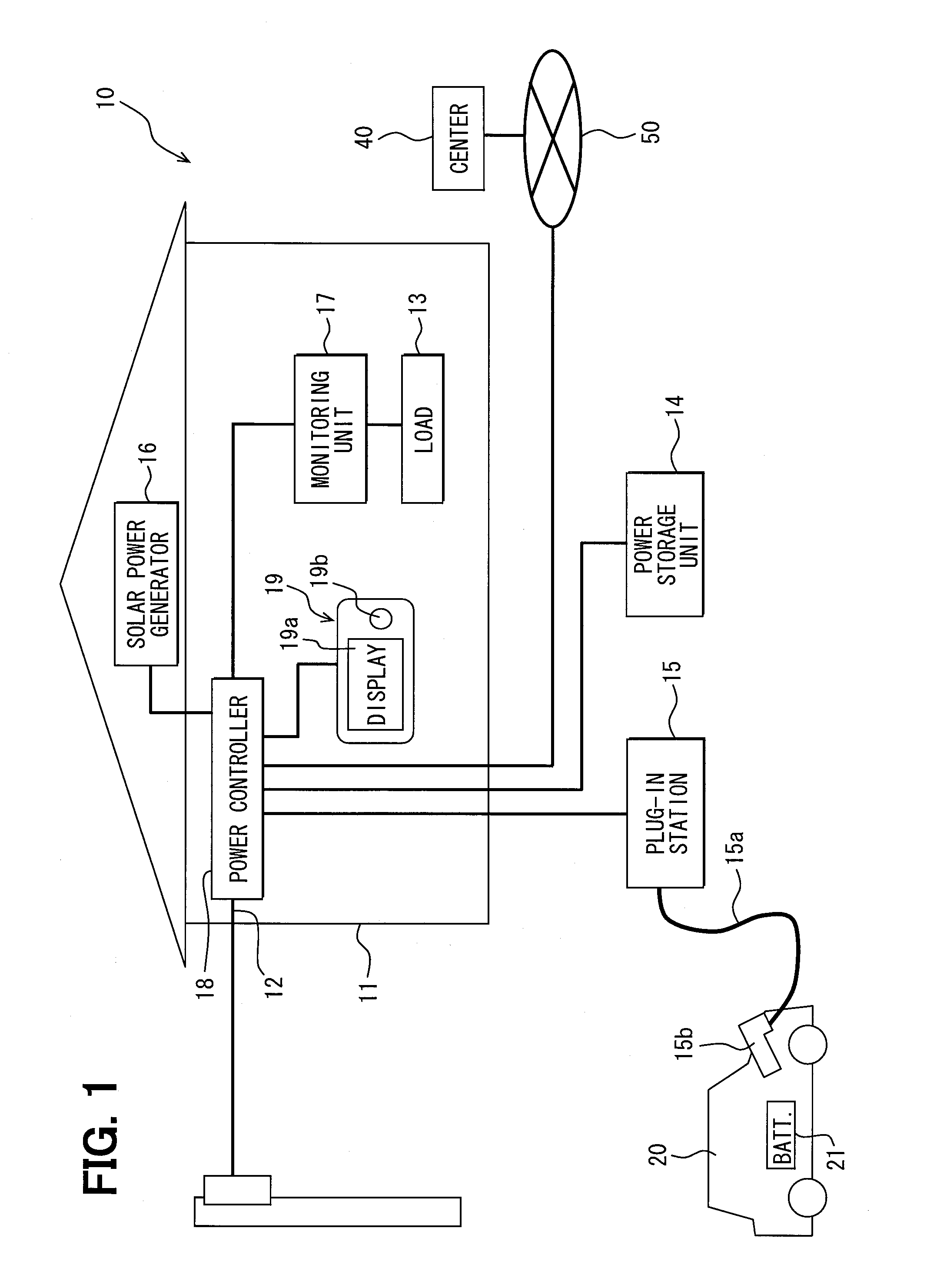
[0024]A power supply system 10 according to an embodiment of the present disclosure is described below with reference to FIGS. 1-15. FIG. 1 is a simplified block diagram of the power supply system 1. In the power supply system 10, a grid power fed from a power grid of a power supplier under a power supply contract is supplied to a general electric load 13 connected to an alternating current (AC) power line 12 wired in a building 11 such a house.

[0025]The power supply system 10 includes the AC power line 12, a power storage unit 14 electrically connected to the AC power line 12, a plug-in station 15 (i.e., power charging station) for charging a vehicle battery 21 by supplying power from the AC power line 12 to a vehicle 20, a solar power generator 16 for generating power from sunlight, the load 13 electrically connected to the AC power line 12, a monitoring unit 17 for monitoring power consumption of the load 13, an integrated power controller 18 for controlling each component, and a...


PUM


Abstract

A power supply system for supplying a grid power to a building includes a power generator, a power storing device, and a power controller. The power generator generates off-grid power from a predetermined energy. The power storing device stores the grid power and the off-grid power and supplies the stored power to the building. The power controller controls consumptions of the grid power and the off-grid power. The power controller calculates predicted consumption data related to power consumed in the building and predicted generation data related to power generated by the power generator. The power controller calculates a charging-discharging schedule for the power storing device based on the predicted consumption data and the predicted generation data by formulating the charging-discharging schedule as a mixed integer programming problem.

Description

CROSS REFERENCE TO RELATED APPLICATION[0001]This application is based on Japanese Patent Application No. 2011461465 filed on Jul. 24, 2011 the disclosure of which is incorporated herein by reference.TECHNICAL FIELD[0002]The present disclosure relates to a power supply system for controlling charging and discharging of a power storing device based on the amount of power consumed and the amount of power generated by a generator such as a solar power generator.BACKGROUND[0003]In recent years, there has been a demand for a method of minimizing electric bill and carbon dioxide emissions in a building, where multiple power supply sources including a utility grid and a solar power generator and multiples batteries including a power storage unit installed at the building and a vehicle battery mounted on a vehicle are available. In a power supply system disclosed in US 2009 / 0192655 corresponding to JP 2008-54439A, power exchanged between a vehicle and a building is managed by taking into acc...

Claims


Application Information

Patent Timeline
IPC IPC(8): G06F1/26
CPCY02T10/7088Y02T10/7291Y02T90/16Y02T90/163Y02T90/169Y02T90/121Y02T90/14Y02T90/128Y04S10/126Y04S30/14Y02E60/721B60L3/12B60L11/1816B60L11/184B60L11/1842B60L11/1844B60L11/1846B60L2230/16B60L2230/22B60L2240/66Y02T10/7005B60L53/14B60L53/64B60L55/00B60L53/63B60L53/65B60L53/305B60L53/51Y02E60/00Y02T10/70Y02T10/7072Y02T10/72Y02T90/12Y02T90/167
Inventor ITO, AKIRAKANAMORI, JUNICHIROUFUJITA, MITSURUSUZUKI, TATSUYAINAGAKI, SHINKICHISUMIYA, MASAHIROYAMAGUCHI, TAKUMA
Owner DENSO CORP
Why Eureka
Try Eureka