Radio frequency circuit

Inactive Publication Date: 2013-01-31
SHENZHEN FUTAIHONG PRECISION IND CO LTD +1
View PDF11 Cites 9 Cited by
  • Summary
  • Abstract
  • Description
  • Claims
  • Application Information

AI Technical Summary

Benefits of technology

This patent is about a circuit that reduces interference in signals. It is designed to improve the performance of integrated circuits.

Problems solved by technology

However, this layout and design may easily result in signal transmission in each adjacent signal line being interfered with, thus reducing signal communication quality of the mobile terminals.

Method used


Image

  • Radio frequency circuit
  • Radio frequency circuit

Examples


Embodiment Construction

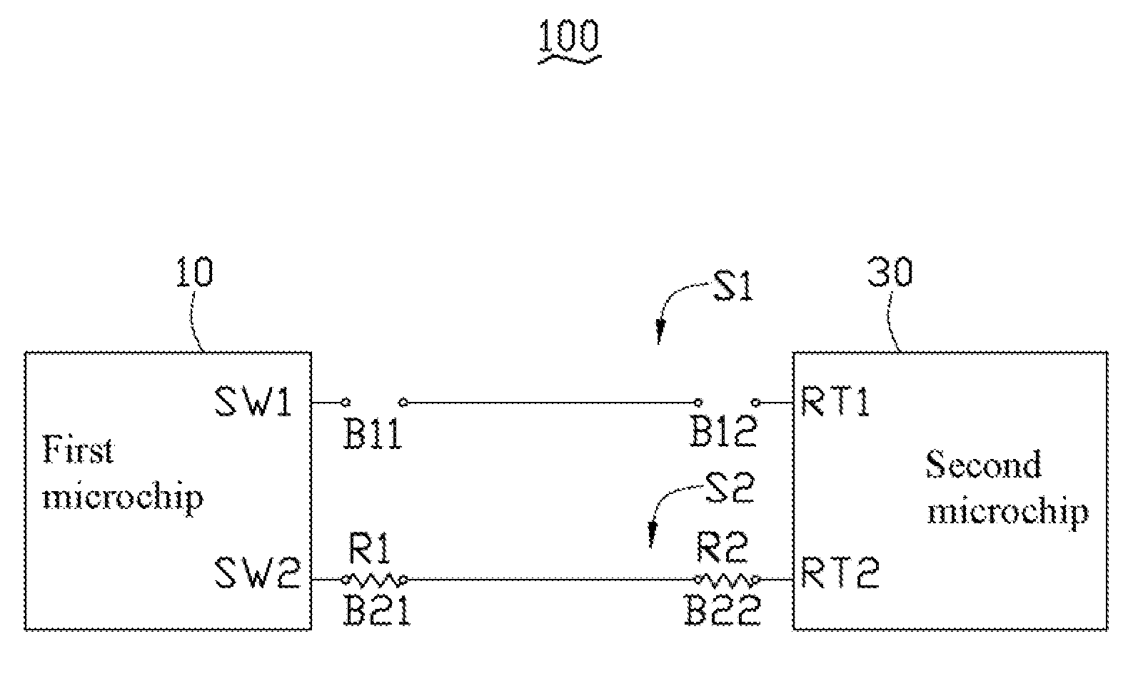
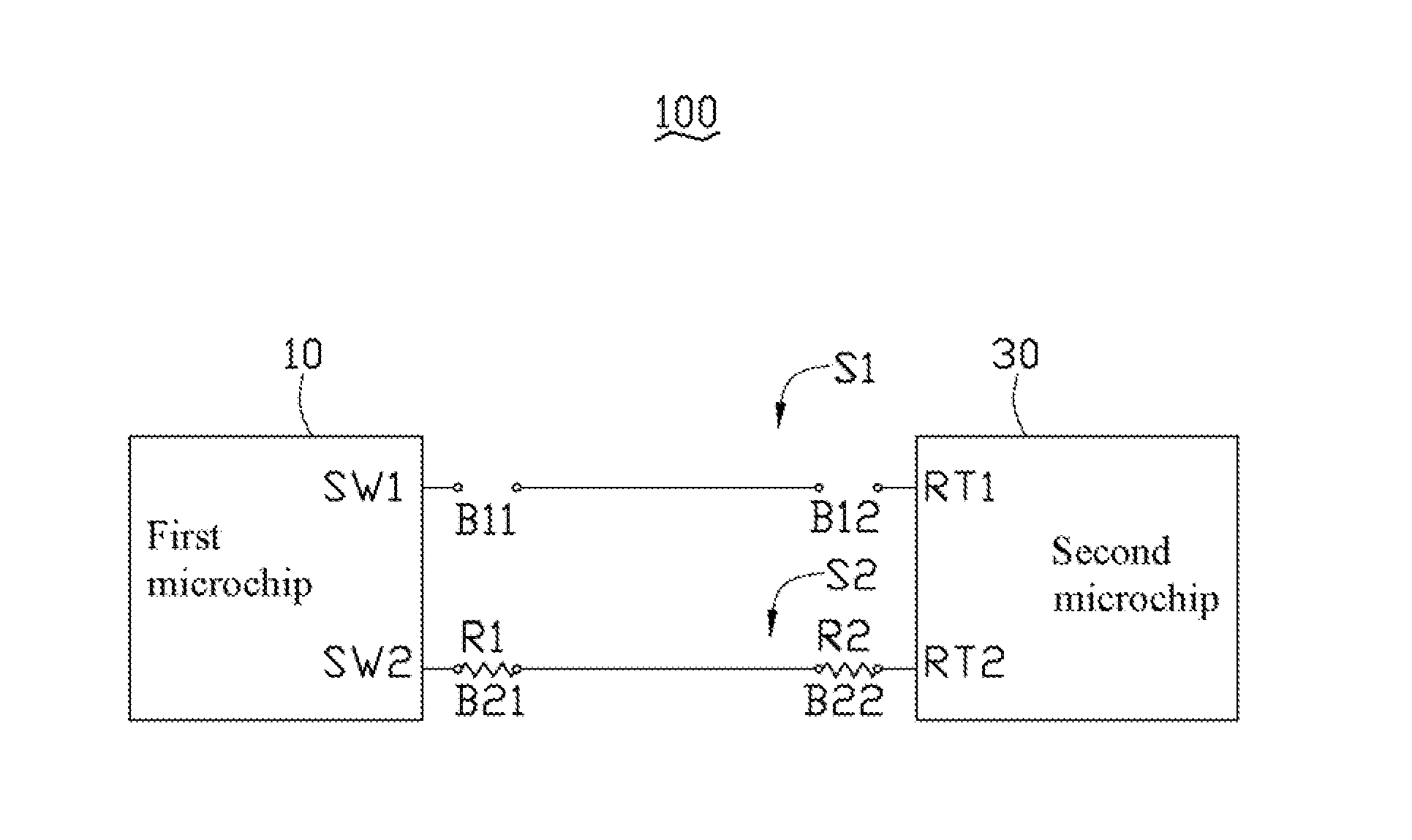
[0008]The drawing is a circuit view of one embodiment of a radio frequency (RF) circuit 100 of the disclosure. The RF circuit 100 can be used in various types of mobile terminals, such as mobile phones, to reduce signal interference when the RF circuit 100 is transmitting and receiving RF signals of different radio communication bands.

[0009]The RF circuit 100 includes a first microchip 10, a second microchip 30, at least two signal lines, a first resistor R1, and a second resistor R2. Each signal line has opposite first and second ends, and each first end of each signal line is electrically connected to the first microchip 10, and each second end of each signal line is electrically connected to the second microchip 30. In this embodiment, the RF circuit 100 includes a first signal line S1 and a second signal line S2. The first microchip 10 can be an antenna switch, and includes a first signal transmission terminal SW1 and a second signal transmission terminal SW2. The second microch...


PUM


Abstract

A radio frequency (RF) circuit includes a first microchip for transmitting RF signal, a second microchip, two resistors and at least two signal lines. Each signal line has opposite first and second ends, and each first end of each signal line is connected to the first microchip and each second end of each signal line is connected to the second microchip. Each signal line defines first and second gaps, the first gaps are adjacent to the first microchip and the second gaps are adjacent to the second microchip. The two resistors are selectively located at the gaps of any one signal line, whereby the first microchip and the second microchip are connected to each other through the signal line and the resistors to form a connection path.

Description

BACKGROUND[0001]1. Technical Field[0002]The disclosure generally relates to integrated circuits, and more particularly to a radio frequency circuit used for reducing interference in signals.[0003]2. Description of the Related Art[0004]Radio frequency (RF) circuits are used within many mobile terminals such as mobile phones to transmit radio signals of different communication bands. The RF circuit usually includes signal lines which may be disposed and laid out close together to receive or transmit radio signals at different communication bands. However, this layout and design may easily result in signal transmission in each adjacent signal line being interfered with, thus reducing signal communication quality of the mobile terminals.[0005]Therefore, there is room for improvement within the art.BRIEF DESCRIPTION OF THE DRAWINGS[0006]Many aspects of a radio frequency circuit can be better understood with reference to the drawing. The components in the drawing are not necessarily drawn...

Claims


Application Information

Patent Timeline
IPC IPC(8): H01B11/00
CPCH04B1/0067G11B7/24038G11B7/2492
Inventor WANG, XIAO-DONGDONG, HANGCHEN, YA-NANFENG, JIAN-YAN
Owner SHENZHEN FUTAIHONG PRECISION IND CO LTD
Why Eureka
Try Eureka