Motor control method

Active Publication Date: 2013-01-31
SUNONWEALTH ELECTRIC MACHINE IND
View PDF3 Cites 1 Cited by
  • Summary
  • Abstract
  • Description
  • Claims
  • Application Information

AI Technical Summary

Benefits of technology

The invention provides a way to control a motor using PWM signals for both direction and speed without needing to modify the motor control system. This makes it easy to implement, low power consumption, low fault possibility, and reduces the space and complexity of the motor control system.

Problems solved by technology

However, dust coming along with the airflow drawn into the electric device can be easily accumulated inside the electric device.
However, there are still some drawbacks of the conventional motor control method waiting to be overcome.
However, in some motor control systems that only generates a PWM signal, a circuit of this motor control system has to be modified for the additional direction control function since the PWM signal only includes the speed command.
In other words, the conventional motor control method cannot be implemented by these motor control systems unless a circuit modification is done, and this will limit the use of the conventional motor control method apparently.
It is known that the strength of a signal decays corresponding to a transmitted distance of the signal, and thus the transmission of the direction signal and the speed signal may result in a power consumption higher than that of a single signal including both the direction and speed commands.
Therefore, a possibility of incorrect operation of this conventional motor control method is higher than that of a motor control method using only a signal including both the direction and speed commands.

Method used


Image

  • Motor control method
  • Motor control method
  • Motor control method

Examples


Embodiment Construction

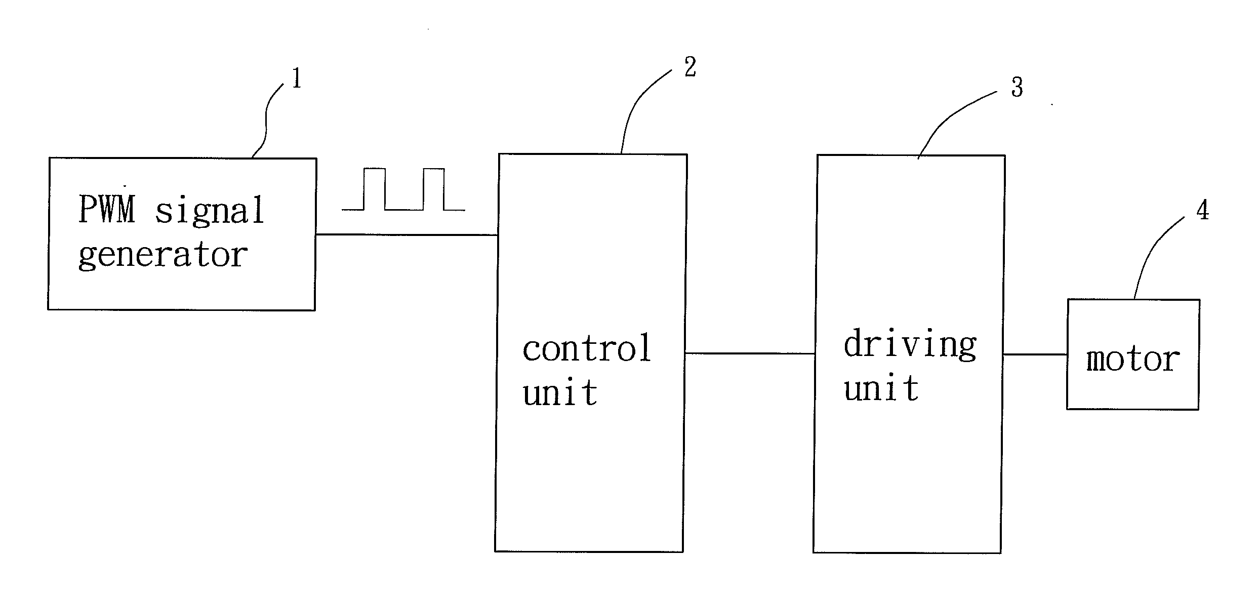
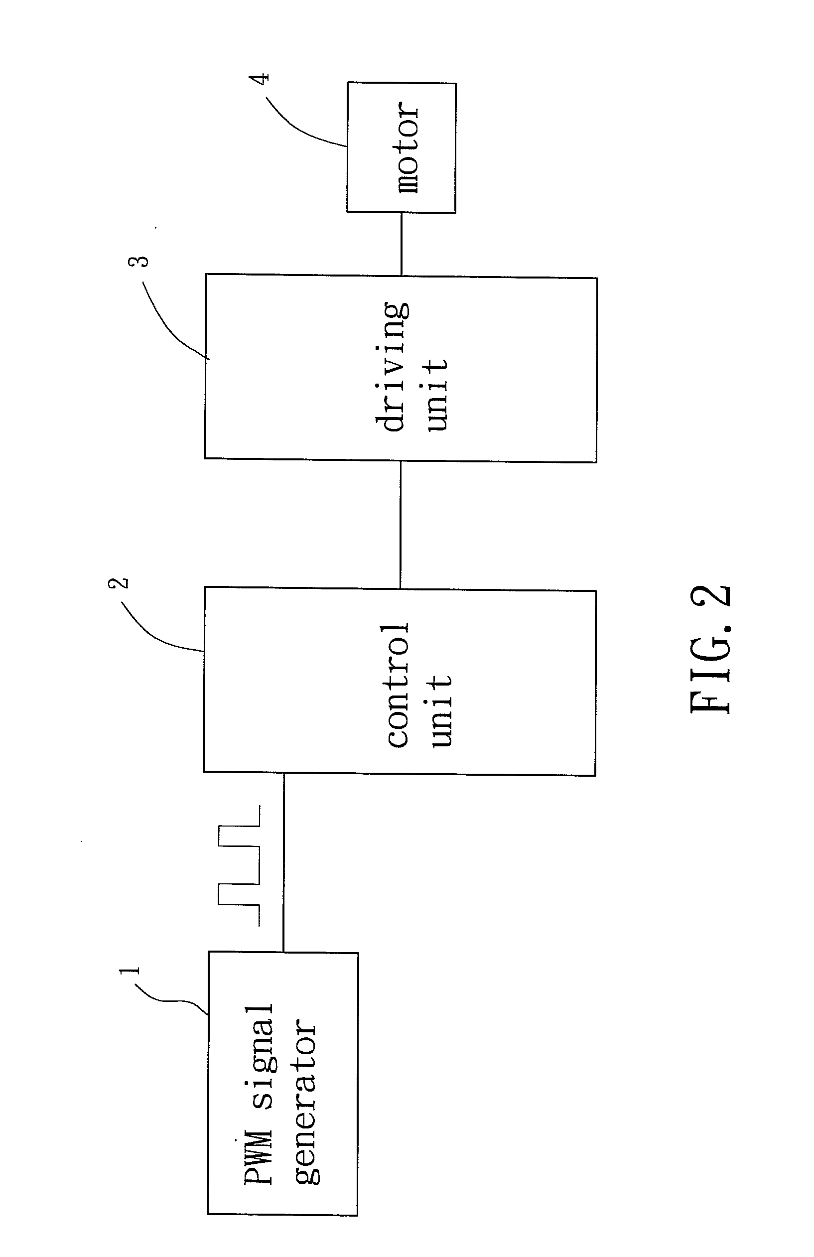
[0029]Referring to FIG. 2, a system for implementing a motor control method of a preferable embodiment of the present invention is shown, which includes a PWM signal generator 1, a control unit 2, a driving unit 3 and a motor 4. The PWM signal generator 1 generates a PWM signal including a direction command and a speed command, wherein the direction command corresponds to a desired rotational direction of the motor 4 and the speed command corresponds to a desired rotational speed of the motor 4. The control unit 2 electrically connects with the PWM signal generator 1 for the PWM signal to be inputted into the control unit 2. Therefore, the control unit 2 can receive the direction and speed commands from the PWM signal and generate a control signal according to the received direction and speed commands. The driving unit 3 electrically connects with the control unit 2 and the motor 4, so that the control signal can be inputted into the driving unit 3 for the driving unit 3 to generate...


PUM


Abstract

A motor control method comprises: inputting a PWM signal into a control unit for the control unit to obtain a direction command and a speed command by an identification rule, and generating a control signal according to the direction and speed commands by the control unit; and generating a driving signal according to the control signal by the driving unit for driving a motor to operate according to the direction and speed commands.

Description

BACKGROUND OF THE INVENTION[0001]1. Field of the Invention[0002]The present invention generally relates to a motor control method and, more particularly, to a motor control method capable of controlling the rotational speed and rotational direction of a motor by a single signal.[0003]2. Description of the Related Art[0004]Conventionally, a fan wheel of a fan in an electric device is usually designed to be rotated in a predetermined direction by a motor of the fan for efficiently dissipating the heat generated during operation of the electric device. However, dust coming along with the airflow drawn into the electric device can be easily accumulated inside the electric device. Therefore, the motor usually drives the fan wheel to rotate in a reverse direction opposite to the predetermined direction for a while, such as 5 seconds, after the electric device is just started so as to execute a dust-removing process for the electric device, and then drives the fan wheel to rotate in the pr...

Claims


Application Information

Patent Timeline
IPC IPC(8): G08C19/16
CPCH02P23/0072H02P23/0068H02P23/22H02P23/24
Inventor CHEN, TUNG-ANLEE, CHIEH-FENGJIAN, DENG-SHANLIN, WEN-CHIEH
Owner SUNONWEALTH ELECTRIC MACHINE IND
Why Eureka
Try Eureka